
Image information processing method and apparatus

An image information processing and image-in-image technology, applied in image data processing, image analysis, electrical digital data processing, etc., can solve the problems of misdetection of the peripheral part of the sclera, decreased detection accuracy, measurement error, etc. The effect of accurate gaze direction measurement

Inactive Publication Date: 2010-02-03
HITACHI LTD +1
View PDF1 Cites 12 Cited by
  • Summary
  • Abstract
  • Description
  • Claims
  • Application Information

AI Technical Summary

Problems solved by technology

[0006] However, in the technology disclosed in Patent Document 1, the angle between the center position of the eyeball and the center position of the pupil is measured to measure the line of sight direction of the person, but there is no disclosure of the method for detecting the center position of the pupil. Specific technical methods
[0007] In addition, in the technology disclosed in Patent Document 2, it is necessary to detect the outline of the iris, but the actual iris is partially covered by the eyelids, so the overall shape of the iris (shape of the outline) does not appear on the image
Therefore, it is difficult to detect the overall shape of the contour of the iris from the above image
[0008] For example, when image processing such as the above-mentioned elliptical Hough transform is performed to detect the outline of the iris from an image of a person, only the outline of the iris that appears on the image may be detected because the entire outline of the iris does not appear on the image. Part of such a bad situation, or a bad situation like the peripheral part of the sclera part being misdetected
As a result, there is a problem in that the detection accuracy of the center position of the pupil which depends on the contour detection of the iris is also reduced, and a large error occurs in the measurement of the gaze direction of the person in the above-mentioned image.

Method used


Image

  • Image information processing method and apparatus
  • Image information processing method and apparatus
  • Image information processing method and apparatus

Examples


Embodiment Construction

[0050] Hereinafter, embodiments of the present invention will be described in detail with reference to the drawings.

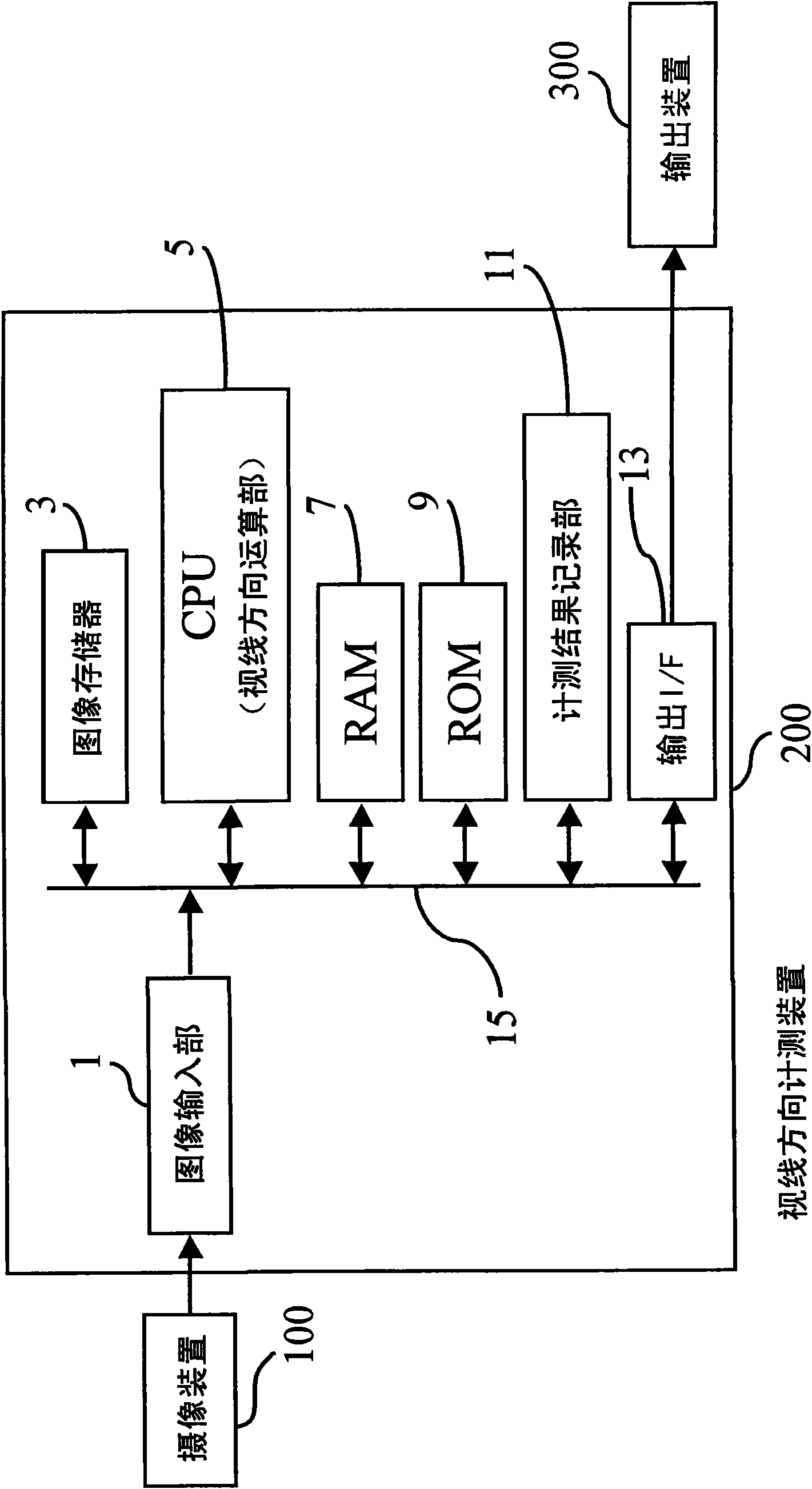
[0051] figure 1It is a functional block diagram showing the overall configuration of the image information processing system according to the first embodiment of the present invention.

[0052] The above-mentioned image information processing system such as figure 1 As shown, an imaging device 100 , a gaze direction measuring device 200 , and an output device 300 are provided. The gaze direction measurement device 200 includes an image input unit 1, an image memory 3, a gaze direction calculation unit (CPU) 5, a RAM 7, a ROM 9, a measurement result recording unit 11, and an output interface (output I / F) 13. -13) As a structure connected to each other through the bus 15.

[0053] exist figure 1 In the imaging apparatus 100, for example, one or more devices capable of photographing movable objects such as digital video cameras are used. The imaging device 1...


PUM


Abstract

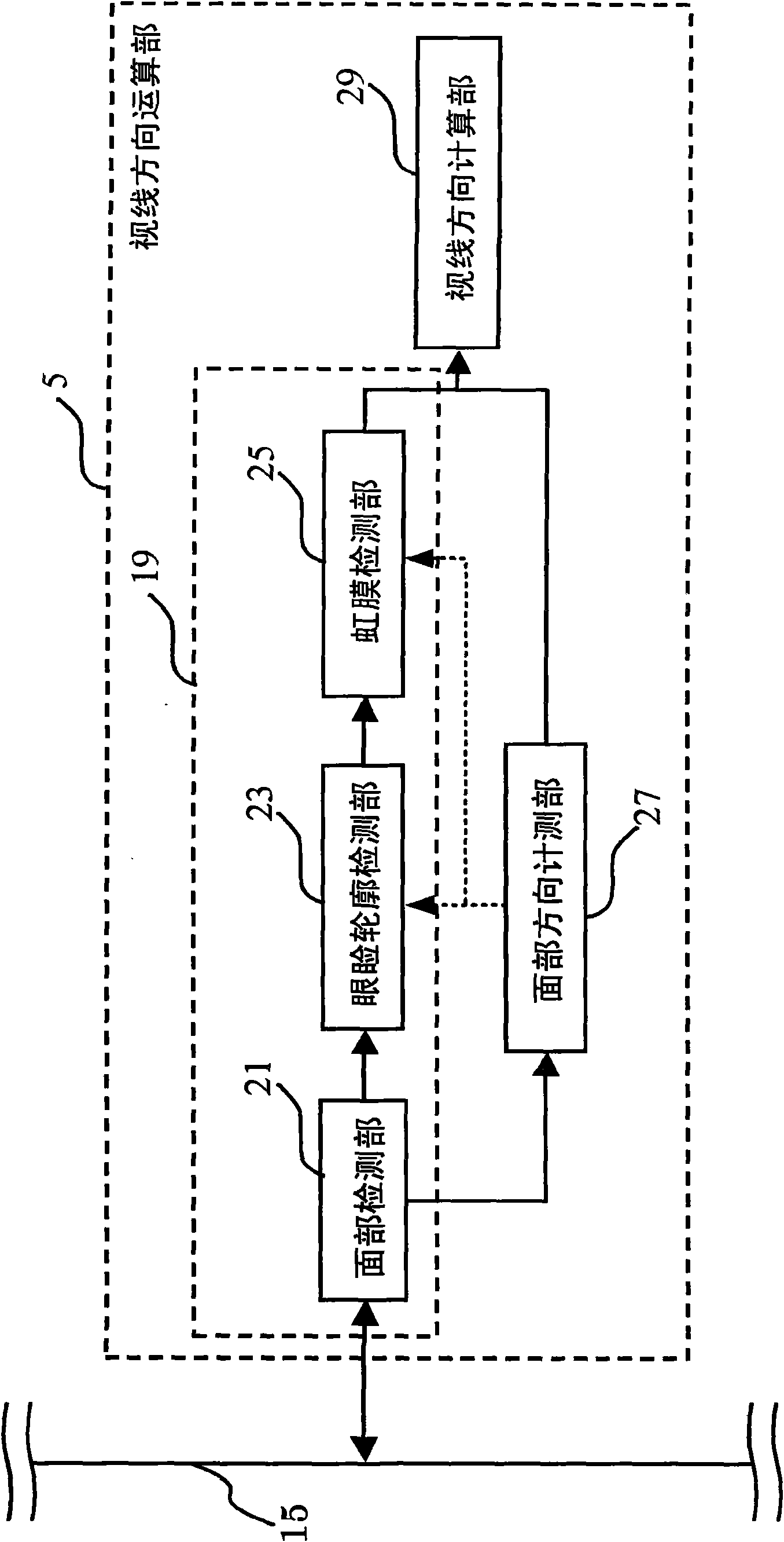
The invention provides an image information processing method and apparatus which can accurately calculate the central position of the iris of the person based on the person image shot and can calculate the sightline direction with the high accuracy. An eye-gaze direction calculation unit (29) calculates the eye-gaze direction in an input facial image of a person by carrying out prescribed operation processing based on iris shape data output from an iris detection unit (25) and face-direction measurement data output from a face-direction measurement unit (27). The eye-gaze direction of the facial image of the person can be measured on the basis of accurate iris shape information obtained by an iris shape detection unit (19). The iris and sclera regions can be estimated on the basis of thedetected eyelid contour information, thereby making it possible to accurately estimate the shape of the iris.

Description

technical field [0001] The present invention relates to an image information processing method and device for detecting a face image area from an input image and performing predetermined image processing operations. Background technique [0002] Conventionally, a method has been developed for the purpose of automatically detecting whether a person in a video is a person with a specific intention (suspicious person). The method carries out the above-mentioned detection by extracting a plurality of information indicating action intentions from the information related to the line of sight direction of the above-mentioned person, and extracts the gaze feature quantity (total gaze time in a specific direction) from the information related to the extracted line of sight direction. , line of sight transition times, average fixation time, glance times or line of sight discrete values, average movement of line of sight, and distance from general line of sight patterns), thereby judgi...

Claims


Application Information

Patent Timeline
IPC IPC(8): G06T7/00G06K9/00
CPCG06F3/013G06K9/0061G06V40/193G06T7/40G06T7/00
Inventor 吉永智明长屋茂喜佐山千春日高英之下川宽之渡边浩司
Owner HITACHI LTD
Learn More