
Identification method of transient state stable key transmission cross-section of electric power system fault

A technology of transient stability and power transmission section, applied in the direction of electrical components, circuit devices, AC network circuits, etc., can solve problems such as not considering transient stability, complicated operation conditions, and at a loss

Active Publication Date: 2010-02-03
NARI TECH CO LTD
View PDF0 Cites 44 Cited by
  • Summary
  • Abstract
  • Description
  • Claims
  • Application Information

AI Technical Summary

Problems solved by technology

At present, the transmission section is often selected by the system dispatcher based on past operating experience, but with the gradual increase in the scale of the power grid, the operation situation becomes more and more complicated, and the dispatcher has to face such a problem: in the current operating state Or in the expected fault scenario, considering the transient stability of the system, if only a small number of transmission sections are monitored online for safety, it is impossible to fully reflect the operating status of the system and find problems and hidden dangers in the current operating state or the power grid under expected faults; If online security monitoring is performed on a large number of transmission sections, dispatchers may be at a loss for a large amount of information
Such methods do not take into account transient stability

Method used


Image

  • Identification method of transient state stable key transmission cross-section of electric power system fault
  • Identification method of transient state stable key transmission cross-section of electric power system fault
  • Identification method of transient state stable key transmission cross-section of electric power system fault

Examples


Embodiment Construction

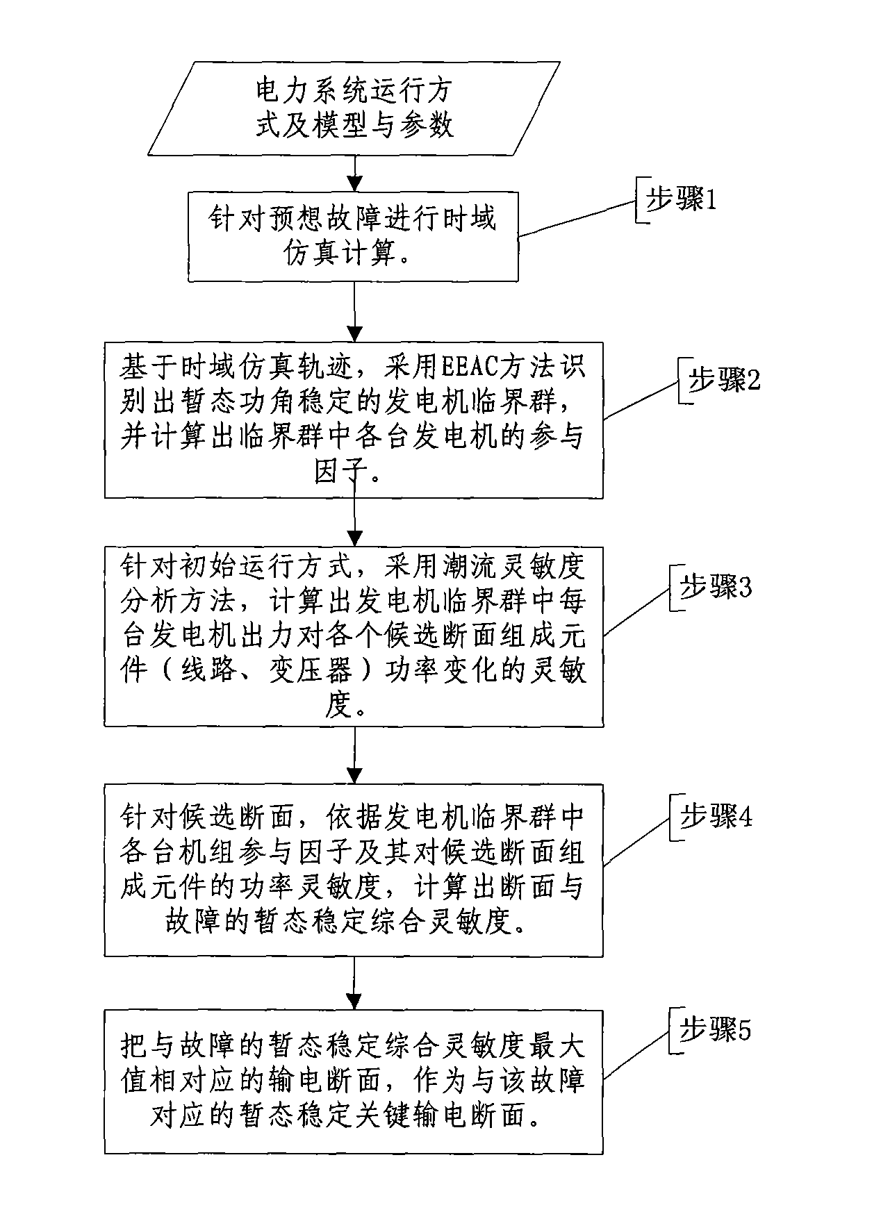
[0016] Attached below figure 1 , the method of the present invention is described in detail.

[0017] figure 1 Step 1 in the above describes the time-domain simulation calculation of the expected fault, that is, according to the power system operation mode and the corresponding model and parameters, for the expected fault, the time-domain simulation method is used to calculate the power system operation trajectory under the expected fault;

[0018] figure 1 Step 2 in the above describes the quantitative evaluation of transient safety and stability based on the expected fault time domain simulation calculation, that is, the critical group of generators is identified by EEAC, and the participation factors of each generator in the critical group are calculated;

[0019] figure 1 Step 3 in the above describes the calculation of the power sensitivity of the generator output to the section, that is, for the initial operation mode, the power flow sensitivity analysis method is use...


PUM


Abstract

The invention provides an identification method of transient state power-angle stable key transmission cross-section corresponding to an expected fault, belonging to the field of electric power systemdispatching automation. Based on a transient state power-angle stable quantitative analysis theory and method, namely extended equal-area criterion (EEAC), the method identifies the key transmissioncross-section corresponding to the expected fault to provide decision support for the electric power system dispatching operation and control. The method comprises the following steps: carrying out atime domain simulation in an expected fault scene based on the operation state, model and parameters of an electric fence; identifying a generator critical group with stable transient state power-angle by EEAC based on simulation track and calculating the participation factor of the generator; calculating the sensitivity to the cross-section components power change caused by the output of each generator in the generator critical group by a power flow sensitivity analysis method; and taking the sum of products of the participation factor in each generator of the generator critical group and corresponding sensitivity of the cross-section component as a judging indicator of the transient state stable key transmission cross-section corresponding to the fault.

Description

technical field [0001] The invention belongs to the field of power system scheduling automation, and determines a key transmission section identification method corresponding to a fault considering the transient stability of the power system according to the operating state of the power grid, a model and parameters, an expected fault scene, and a candidate set of transmission sections. Background technique [0002] The transmission section refers to a group of transmission components (lines, transformers) that are related to each other in terms of grid security and stability or power exchange. From the perspective of power transmission, the active power transmitted by each transmission element in the section should be in the same direction; from the perspective of power exchange, a set of transmission lines connecting two areas constitutes a transmission section for energy exchange. As the channel of power transmission and the corridor of electrical connection, the monitorin...

Claims


Application Information

Patent Timeline
IPC IPC(8): H02J3/00
Inventor 徐泰山鲍颜红李碧君方勇杰薛禹胜杨卫东许剑冰马明
Owner NARI TECH CO LTD
Learn More