Flow sensor

A flow sensor and sensor chip technology, which is applied in the field of flow sensors, can solve problems such as difficult airtight connections, and achieve the effect of easy sealing and miniaturization

Inactive Publication Date: 2010-02-03
YAMATAKE HONEYWELL CO LTD
View PDF4 Cites 5 Cited by
  • Summary
  • Abstract
  • Description
  • Claims
  • Application Information

AI Technical Summary

Problems solved by technology

Therefore, it is difficult to connect the sensor in an airtight manner when installing the sensor on a gas pipeline to be measured.

Method used


Image

  • Flow sensor
  • Flow sensor
  • Flow sensor

Examples


Embodiment Construction

[0058] Next, in order to describe the present invention in more detail, the best mode for carrying out the present invention will be described with reference to the accompanying drawings.

[0059] Embodiment 1

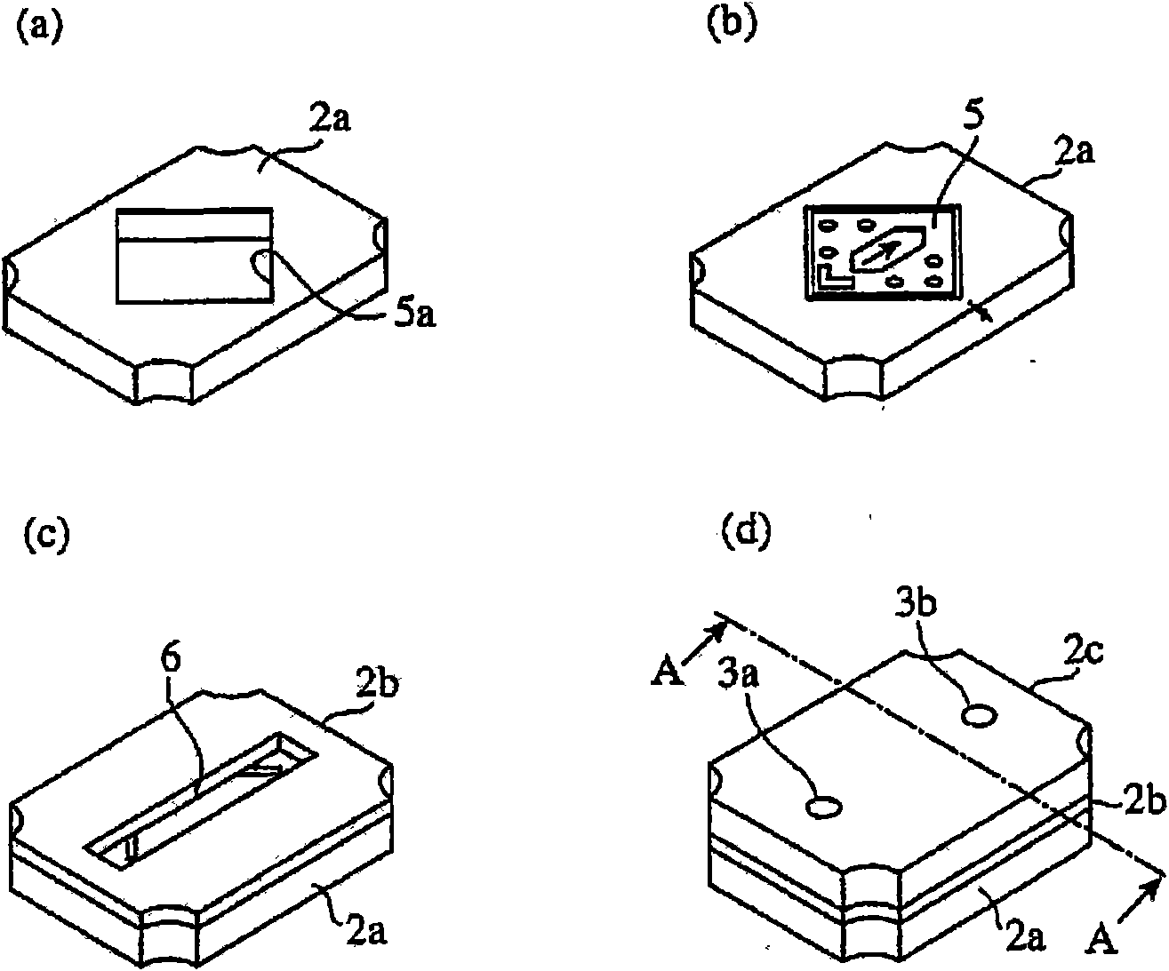
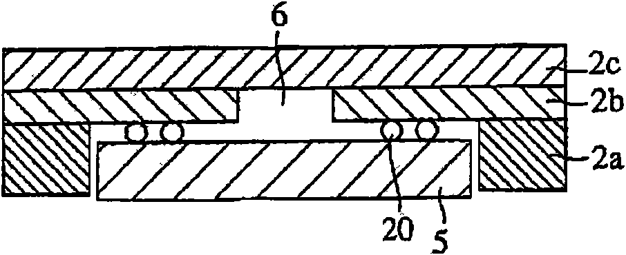
[0060] figure 1 It is a perspective view showing the sensor according to Embodiment 1 of the present invention, and shows a flow sensor configured by accommodating a sensor chip in a package formed by bonding three substrates. Such as figure 1 As shown, in the flow sensor 1 of Embodiment 1, the sensor chip is mounted inside a rectangular package formed by firing and joining ceramic substrates 2a, 2b, and 2c, and the same flat end surface (substrate 2c surface) of the package On the upper side, both the inlet 3a and the outlet 3b of the flow path in the module through which the gas to be measured flows are provided.

[0061] In addition, the substrates 2a to 2c constituting the components of the flow sensor 1 are flat substrates that do not have concavo-convex port...


PUM


Abstract

A package is configured by stacking a flat board (2a) whereupon a rectangular hole (5a) for storing a sensor chip (5) is formed, a flat board (2b) whereupon a hole section (6) to be a package inner channel for introducing a measurement target gas into the sensor chip (5) is formed, and a flat board (2c) whereupon hole sections which communicate with the package inner channel as an inlet (3a) and an outlet (3b) of the measurement target gas on the same end surface of the package are formed.

Description

technical field [0001] The present invention relates to a flow sensor for flow meters and the like. Background technique [0002] In the flow velocity sensor having a module structure disclosed in Patent Document 1, a sensor chip is mounted inside a module in which flat base members are glued together. On the base member, there is provided a groove-shaped flow path parallel to the mounting surface of the sensor chip of the base member, and the inlet and outlet of the flow path are formed on opposite end faces of the module. Furthermore, the electrodes of the sensor chip are electrically connected to the electrodes integrally formed on the base member by wire bonding or solder bumps. [0003] The thermal flowmeter disclosed in Patent Document 2 is configured such that a substrate on which a sensor chip is mounted is brought into close contact with the inner wall of a tubular main body. Grooves parallel to the mounting surface are formed on the sensor chip or substrate, and ...

Claims


Application Information

Patent Timeline
Patent Type & Authority Applications(China)
IPC IPC(8): G01F1/692G01F1/684
CPCG01F5/00G01F1/6842G01F1/6845G01F1/692G01F1/684
Inventor 森田靖二畠山洋志青岛滋藁品勇
Owner YAMATAKE HONEYWELL CO LTD
Why Eureka
Try Eureka