Power control

A technology of constant current power supply and resonant controller, which is applied in the direction of electric light source, electroluminescent light source, control/regulation system, etc., and can solve the problems of high power loss of power amplifier and energy power loss of conduction storage, etc.

Inactive Publication Date: 2014-08-13
INDICE PTY LTD
View PDF6 Cites 5 Cited by
  • Summary
  • Abstract
  • Description
  • Claims
  • Application Information

AI Technical Summary

Problems solved by technology

[0006] 2. When a switch such as a FET is switched on or off, and if current or voltage is in or through the FET, the switching period results in both current and voltage being applied to said FET, which is equivalent to power loss
[0009] Every time the FET turns on in this condition the stored energy is dissipated causing a power loss
[0010] 4. Gate drive losses in an RC equivalent circuit form, where C is the gate capacitance and R is the through-gate resistance
And this power amplifier will generate a lot of power loss

Method used


Image

  • Power control
  • Power control
  • Power control

Examples


Embodiment Construction

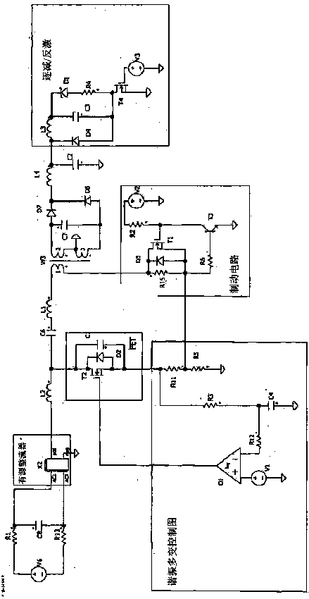
[0047] With reference to the accompanying drawings of this preferred embodiment, as figure 2 As shown, the present invention provides a class E amplifier having the following parts

[0048] A. Resonance Tracking

[0049] B. Brake circuit

[0050] C. Rectifier

[0051] D. Decrease Circuit / Flyback Circuit

[0052] A: Resonance Tracking

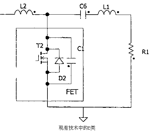
[0053] like figure 1 A specific form of power control in Class E amplifiers. A standard class E amplifier which has a FET on which the transistor (T2) is connected to the load (R1) through a series LC circuit and also to the supply voltage through a large inductor (L2) (not shown). L2 acts as a rough constant current power supply. A capacitor (C1) added to a Class E amplifier connects the transistor output to ground. And such a power amplifier will generate a large amount of power loss.

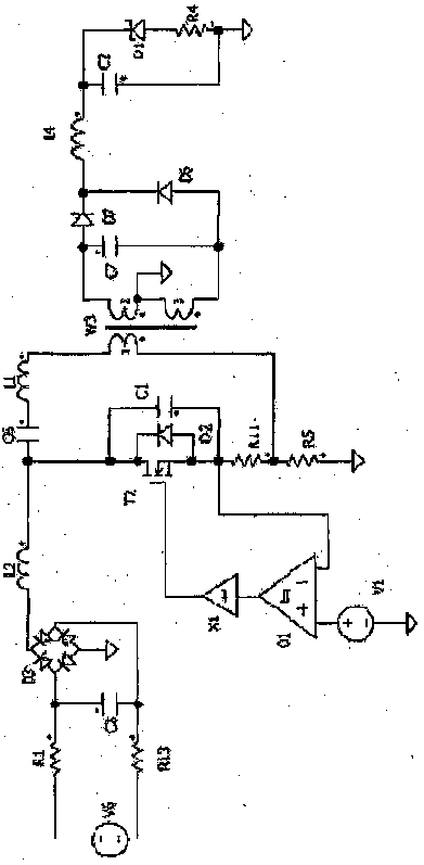
[0054] However this extends to AC applications, either low or high voltage such as image 3 As shown, here the new rectifier consists of components...


PUM


Abstract

A Class E amplifier having a FET with a transistor (T2) connected via a serial "LC" circuit to the load, and connected to a supply voltage via a constant current source, the amplifier further including a resonant controller, wherein the resonant controller provides power control for an AC application and includes a resonance tracking system of an input inductor being fed by a power source with the resonance tracking system using a resistor resonance detector having two sense resistor loads in series.

Description

technical field [0001] The invention relates to power control, in particular to realizing power control through different control switches. More specifically, but not limited thereto, the present invention provides improved methods of power control in silicon topologies. [0002] Although the invention is applicable to a range of power supplies from low voltage to mains voltage, and for direct current or alternating current (DC or AC), for convenience, the invention should be applied to light-emitting diode (LED) power at a range of voltages. Control the narrative. In particular, Class E amplifiers will be addressed. However, the scope of the present invention is not limited thereto and may include other power control one or more parts. Background technique [0003] In the power control circuit, the focus is on power loss and storage. In a switch mode power supply, power losses occur in various situations. Some major situations are: [0004] 1. The loss of ohmic power ...

Claims


Application Information

Patent Timeline
Patent Type & Authority Applications(China)
IPC IPC(8): H02M3/335H02M7/539
CPCY02B20/347Y02B70/1433H03F3/2176H05B33/0815H02M7/49H02M2001/0003H02M3/335H05B45/375H05B45/385H02M1/0003Y02B20/30Y02B70/10H02M1/0058
Inventor 詹姆斯·哈蒙德
Owner INDICE PTY LTD
Why Eureka
Try Eureka