Multifunctional hydraulic gravel breaking hammer and manufacturing method thereof

A multifunctional, breaking hammer technology, applied in the field of robots, can solve the problems that the breaking hammer cannot quickly capture the force point and impact direction of the crushed object, and the working efficiency of the hydraulic breaking hammer is low, so as to improve the working efficiency of breaking, avoid shaking, Apply a wide range of effects

Pending Publication Date: 2018-05-01
宣城市安工大工业技术研究院有限公司
View PDF2 Cites 3 Cited by
  • Summary
  • Abstract
  • Description
  • Claims
  • Application Information

AI Technical Summary

Problems solved by technology

[0006] Aiming at the structural limitation of the existing hydraulic breaker/hammer, which causes the breaker to be unable to quickly capture the force point and impact direction of the crushed object, resulting in low working efficiency of the hydraulic breaker, the present invention

Method used


Image

  • Multifunctional hydraulic gravel breaking hammer and manufacturing method thereof
  • Multifunctional hydraulic gravel breaking hammer and manufacturing method thereof
  • Multifunctional hydraulic gravel breaking hammer and manufacturing method thereof

Examples


Example Embodiment

[0036] Example 1

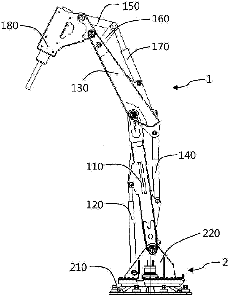
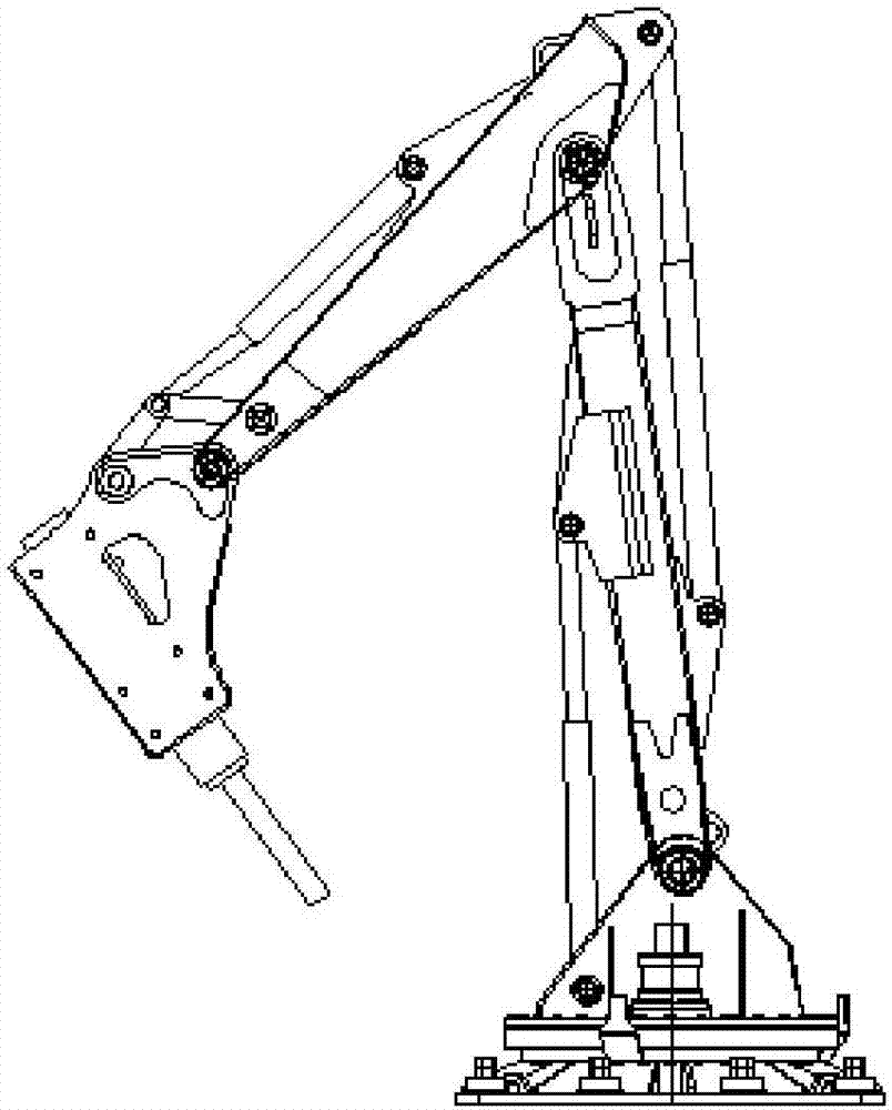
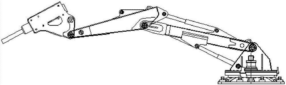
[0037] Such as Figure 1 to Figure 3 As shown, the multifunctional hydraulic rock breaking hammer of this embodiment includes a plane luffing mechanism 1 and a rotating mechanism 2. The plane luffing mechanism 1 includes a boom 110, a boom cylinder 120, a small arm 130, a forearm cylinder 140, a rocker 150, a connecting rod 160, a hydraulic hammer cylinder 170, and a hydraulic hammer 180. The hydraulic hammer 180 adopts a full hydraulic mechanism; The slewing mechanism 2 includes a base 210 and a slewing seat 220, wherein the bottom of the boom 110 is fixed on the slewing seat 220, the cylinder block of the boom cylinder 120 is fixed on the slewing seat 220, the piston rod is hinged with the boom 110, and the arm 130 The middle is hinged to the front end of the boom 110, the cylinder body of the forearm cylinder 140 is hinged to the middle of the boom 110, the piston rod is hinged to the upper end of the forearm 130, and the lower end of the forearm 130 is hin...

Example Embodiment

[0042] Example 2

[0043] The manufacturing method of the multifunctional hydraulic rock crushing hammer of this embodiment includes the following specific steps:

[0044] Step S101. Ingredients: Weigh and mix the components of the big arm or the forearm according to mass percentages, where the component mass percentages are: C: 0.19%, Mn: 0.59%, Si: 0.25%, Co: 0.5% , Cr: 1.4%, V: 1.13%, Ni: 1.02%, S: 0.020%, P: 0.020%, the balance is Fe; the blank of the big arm or forearm passes through the first stage: room temperature~560℃: the blank Heat from room temperature to 560℃, heating time is 60min; second stage: 560℃~780℃: heat the billet from 560℃ to 780℃, control heating time to 20min, hold 80min; third stage: 780℃~1200℃ : Heat the billet from 780°C to 1200°C, control the heating time to 70min, keep the temperature for 45min; the fourth stage: 1200°C~1350°C: Heat the billet from 1200°C to 1350°C, control the heating time to 20min, keep the temperature for 40min, heat treatment Aft...

Example Embodiment

[0049] Example 3

[0050] The manufacturing method of the multifunctional hydraulic rock crushing hammer of this embodiment includes the following specific steps:

[0051] Step S101. Ingredients: Weigh and mix the components of the big arm or the forearm according to mass percentages, where the component mass percentages are: C: 0.20%, Mn: 0.75%, Si: 0.35%, Co: 0.6% , Cr: 1.47%, V: 1.03%, Ni: 1.22%, S: 0.020%, P: 0.020%, the balance is Fe; the blank of the big arm or forearm passes the first stage: room temperature ~ 560℃: the blank Heat from room temperature to 560℃, heating time is 45min; second stage: 560℃~780℃: heat the billet from 560℃ to 780℃, control the heating time to 20min, hold 65min; third stage: 780℃~1200℃ : Heat the billet from 780°C to 1200°C, control the heating time to 65min, hold 40min; the fourth stage: 1200°C~1350°C: Heat the billet from 1200°C to 1350°C, control the heating time to 20min, hold 40min, heat treatment After the blank, there are almost no system ...


PUM


Abstract

The invention discloses a multifunctional hydraulic gravel breaking hammer and a manufacturing method thereof, and belongs to the technical field of robots. A plane amplitude changing mechanism of themultifunctional hydraulic gravel breaking hammer comprises a big arm, a big arm oil cylinder, a small arm, a small arm oil cylinder, a rocker, a connecting rod, a hydraulic hammer oil cylinder and ahydraulic hammer. A rotation mechanism comprises a base and a rotation base, the bottom of the big arm is fixed to the rotation base, a cylinder body of the big arm oil cylinder is fixed to the rotation base, a piston rod is hinged to the big arm, the middle portion of the small arm is hinged to the front end of the big arm, a cylinder body of the small arm oil cylinder is hinged to the middle portion of the big arm, and the piston rod is hinged to the upper end of the small arm. The lower end of the small arm is hinged to the hydraulic hammer. The two ends of the connecting rod are connectedwith the lower portion of the small arm and a piston rod of the hydraulic hammer oil cylinder correspondingly, and the two ends of the rocker are hinged to the connecting rod and the upper portion ofthe hydraulic hammer correspondingly. By means of the multifunctional hydraulic gravel breaking hammer and the manufacturing method thereof, broken objects, hammering points and hammering directions can be rapidly captured in the three-dimensional space, the breaking range is large through rotation around the rotation base, positioning of a hammer head of the hydraulic hammer is accurate, and thebreaking work efficiency is effectively improved.

Description

technical field [0001] The invention belongs to the technical field of robots, and more specifically relates to a multifunctional hydraulic rock breaking hammer and a manufacturing method thereof. Background technique [0002] The engineering hydraulic breaker is a combination of machine, electricity and hydraulic technology. By converting the hydraulic energy into the mechanical energy of the hydraulic breaker, the large and hard materials are crushed under the impact of the hammer head and the drill rod, and the crushing is completed. Task. The power source of the hydraulic breaker is the pressure provided by the excavator, loader or pump station, which can more effectively break stones and rocks in engineering construction and improve work efficiency. [0003] The essence of the working principle of the hydraulic breaker is the mutual feedback control of the impact piston and the control valve to realize the reciprocating linear motion of the impact piston in the body, t...

Claims


Application Information

Patent Timeline
IPC IPC(8): B02C1/00B02C1/14E02F5/30C22C38/02C22C38/04C22C38/52C22C38/46C21D6/00
CPCC21D6/004C21D6/005C21D6/007C21D6/008C22C38/02C22C38/04C22C38/46C22C38/52E02F5/305B02C1/005B02C1/14
Inventor 宋崇智
Owner 宣城市安工大工业技术研究院有限公司
Why Eureka
Try Eureka