an engine cooling system

A technology for engine cooling and engine block, which is applied in the direction of engine cooling, engine components, machines/engines, etc., can solve engine cooling and other problems, and achieve the effects of emission optimization, fuel economy improvement, and cooling effect improvement

Active Publication Date: 2011-12-14
CHERY AUTOMOBILE CO LTD
View PDF0 Cites 2 Cited by
  • Summary
  • Abstract
  • Description
  • Claims
  • Application Information

AI Technical Summary

Problems solved by technology

At present, there is no engine manufacturer in China that can solve the above two shortcomings of engine cooling.
These two aspects have always puzzled engine manufacturers, and have not yet resolved them.

Method used


Image

  • an engine cooling system
  • an engine cooling system
  • an engine cooling system

Examples


Embodiment Construction

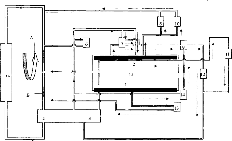
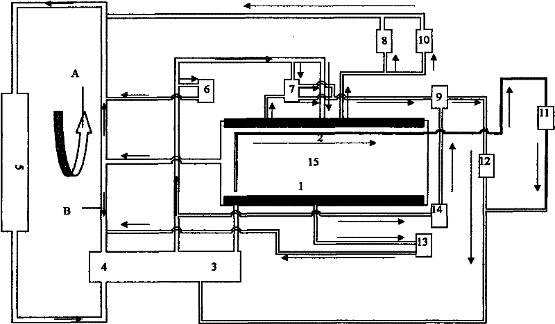
[0019] The present invention will be specifically described below in conjunction with the accompanying drawings.

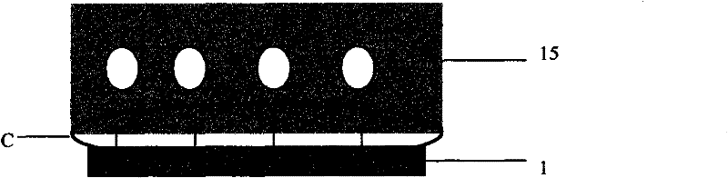
[0020] Such as figure 1 As shown, the thermostat 4 of this cooling system is installed in the inlet type, and the cooling water passes through the water pump 3. Using the centrifugal force, the water pump 3 pumps the water into the two distribution pipes 1 and 2 installed at the lower part of the cylinder, as shown in figure 1 As shown, the distribution pipes 1 and 2 have multiple passages, and each passage corresponds to a cylinder. Cooling water enters the cylinder body through each passage to cool the engine, and then the coolant enters the cylinder head through the cylinder body to cool the engine cylinder head. Then the coolant returns to the water collector through the cylinder head, finally returns to the thermostat 4, and finally returns to the water pump 3, thereby realizing the circulation of the cooling system.

[0021] The water that the water pump 3 ...


PUM


Abstract

The invention discloses an engine cooling system, which is characterized in that: a cooling water distribution pipe is installed on the engine block, and the distribution pipe has a plurality of passages, and one passage corresponds to one cylinder. The cooling water enters the engine block through each channel to cool the engine, and then the coolant enters the cylinder head through the cylinder block to cool the engine cylinder head, and then the coolant returns to the water collector through the cylinder head, and then returns to the thermostat. Eventually back to the water pump. The present invention installs a water distribution pipe under the ordinary engine cylinder, so that each cylinder corresponds to each channel of a water distribution pipe, so that the water intake of each cylinder is the same, and the water intake pressure and water intake speed are the same. In this way, the cooling effect of all the cylinders is guaranteed to be the same, which improves the cooling effect of the engine, and the uniformity of the coolant distribution in the engine block is also improved. The fuel economy of the engine has been improved, and the emission of the engine has been optimized.

Description

technical field [0001] The invention belongs to the field of automobiles, and is particularly suitable for cooling large-displacement automobile engines. Background technique [0002] At present, for most engines, what they use is the common cooling method, that is, from the 1st cylinder to the last cylinder and then the coolant returns from the cylinder head to the thermostat, which leads to the cooling effect of the 1st cylinder and the last cylinder It is relatively poor and also makes the coolant distribution uneven. This makes emissions and fuel economy less than optimal. At present, there is no engine manufacturer in China that can solve the above two engine cooling shortcomings well. These two aspects have been perplexing the engine manufacturers all the time, and they have not been resolved until now. Contents of the invention [0003] In order to solve the above problems, the present invention discloses an engine cooling system, which is characterized in that a...

Claims


Application Information

Patent Timeline
Patent Type & Authority Patents(China)
IPC IPC(8): F02F1/10F01P7/16F01P3/20
Inventor 赵前进
Owner CHERY AUTOMOBILE CO LTD
Why Eureka
Try Eureka