Furnace slow-cooling area structure capable of shrinking cross-sectional temperature difference

A technology of slow cooling zone and cross-section, applied in the direction of furnace cooling, furnace, furnace components, etc., can solve problems such as temperature difference, cold cracking, and insufficient flexural strength of the kiln cross-section, and achieve the goal of reducing the temperature difference of the cross-section and avoiding defects Effect

Active Publication Date: 2013-10-16
MODENA TECH LTD
View PDF6 Cites 2 Cited by
  • Summary
  • Abstract
  • Description
  • Claims
  • Application Information

AI Technical Summary

Problems solved by technology

For the cross-section of the slow cooling zone, this structure will inevitably result in a low temperature at one end of the cold air inlet and a higher temperature at the other end of the hot air outlet, resulting in a temperature difference in the cross-section of the kiln, making multiple rows of products in the same section or large specifications Different positions of the product produce "stress" due to inconsistent cooling rates, and defects such as "cold cracking" and insufficient flexural strength occur

Method used


Image

  • Furnace slow-cooling area structure capable of shrinking cross-sectional temperature difference
  • Furnace slow-cooling area structure capable of shrinking cross-sectional temperature difference
  • Furnace slow-cooling area structure capable of shrinking cross-sectional temperature difference

Examples


Embodiment Construction

[0013] Now set forth the present invention in detail in conjunction with accompanying drawing:

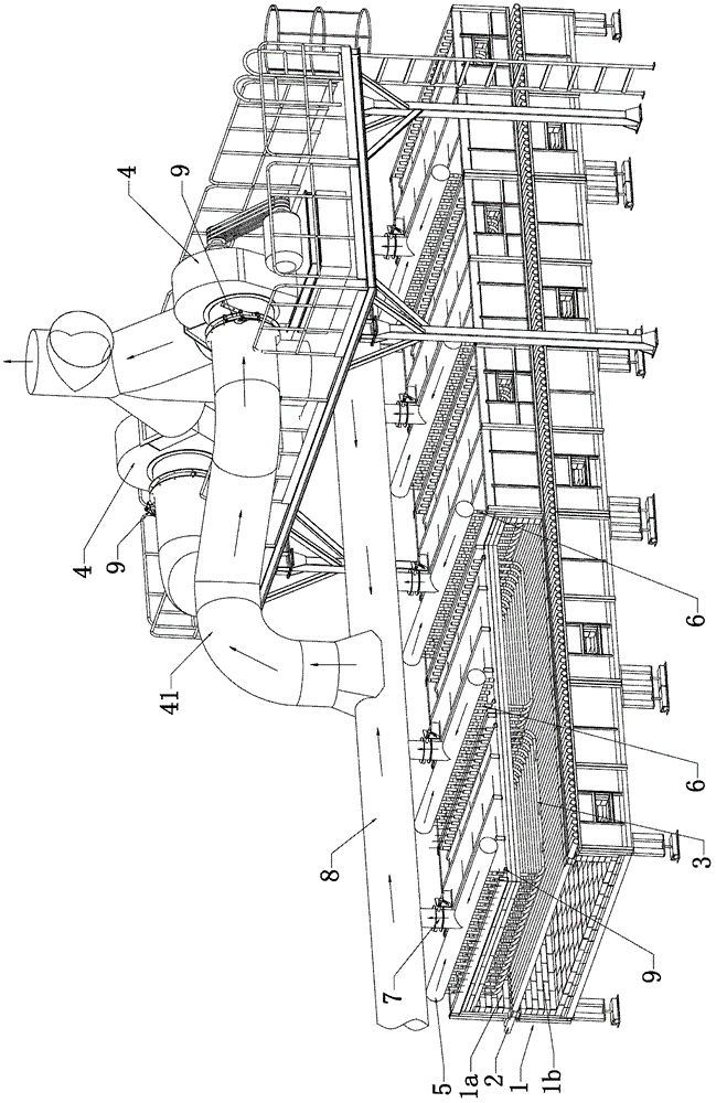
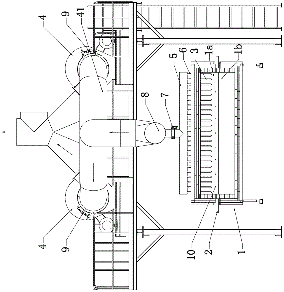
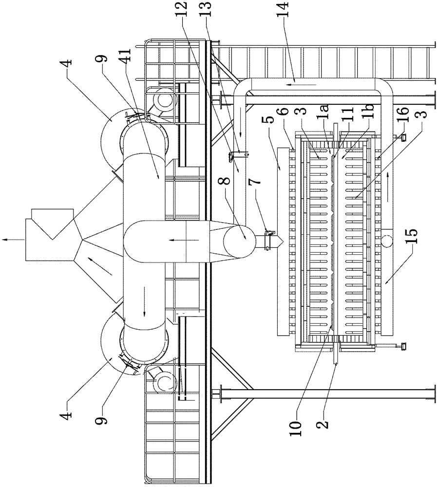
[0014] See attached figure 1 And attached figure 2 As shown, it is the first embodiment of the present invention, including a slow cooling chamber 1, a plurality of conveying rollers 2, a "U"-shaped longitudinal heat exchange tube 3, an exhaust fan 4 and an exhaust branch pipe group 5, and the conveying rollers 2 move along the slow cooling chamber. 1 are arranged in sequence along the length direction, the slow cooling chamber 1 is divided into an upper passage 1a and a lower passage 1b by the conveying roller 2, and the "U"-shaped longitudinal heat exchange tube 3 is in the upper passage 1a in the length direction of the slow cooling chamber 1, and passes from the slow cooling chamber 1 The top of the cold room 1 protrudes, and one end of the "U"-shaped longitudinal heat exchange pipe 3 communicates with the workshop, and the other end is connected with the pipe joint of the ex...


PUM


Abstract

The invention discloses a furnace slow-cooling area structure capable of shrinking cross-sectional temperature differences, which comprises a slow-cooling chamber, a plurality of conveying rollers, a large amount of heat-exchanging pipes and an exhausting mechanism, wherein the exhausting mechanism is communicated with the heat-exchanging pipes, the conveying rollers are sequentially arranged along the length direction of the slow-cooling chamber and are placed at the middle part of the slow-cooling chamber, the heat-exchanging pipes are arranged along the longitudinal direction of the slow-cooling chamber, each heat-exchanging pipe is a U-shaped steel pipe with two open ends, one end of each heat-exchanging pipe is communicated with a workshop, and the other end of each heat-exchanging pipe is communicated with the exhausting mechanism. The furnace slow-cooling area structure has the beneficial effects that the basic sameness of the temperatures of all points on the same cross section is realized; because a wind inlet and a wind outlet are positioned at different positions on the same section, the cooling effects can tend towards consistency under the conditions that the diameters of branched pipes are the same and the flow speeds of hot wind are the same, the cross-sectional temperature difference of a furnace-cooling passage is shrunk, the sameness of the cooling speeds of a product at the slow-cooling stage can be ensured, and the defects of the product caused by cooling temperature differences are avoided.

Description

Technical field: [0001] The invention relates to the technical field of ceramic tile firing, in particular to a slow cooling zone structure of a kiln that can reduce the cross-sectional temperature difference. Background technique: [0002] The ceramic firing process must have a slow cooling stage, the main purpose is to cool down gently in this area, to prevent the rapid volume change (expansion or contraction) of β-quartz ←→ α-quartz at 573°C to cause "wind shock" (cold cracking) ). The existing firing kiln equipment basically adopts a plurality of cooling pipes (or heat exchange pipes) arranged at intervals in the horizontal direction, through the pipe wall, the low-temperature cold air in the pipe and the high-temperature gas in the kiln perform heat exchange to achieve the purpose of cooling the product. The basic method is to pass through the steel pipe across the kiln section (kiln width direction), one end sucks cold air from the workshop and the other end discharge...

Claims


Application Information

Patent Timeline
Patent Type & Authority Patents(China)
IPC IPC(8): F27D9/00F28F1/00
Inventor 吴俊良荆海山陶志坚
Owner MODENA TECH LTD
Why Eureka
Try Eureka