
Cooling system and cooling method for I-shaped steel

A technology of I-shaped steel and cooling system, applied in the direction of furnace types, manufacturing tools, furnaces, etc., can solve the problems of poor cross-section temperature uniformity affecting the stability of finished products, etc., to reduce temperature, improve lamellar spacing and shape, and accelerate cooling speed effect

Active Publication Date: 2022-03-01
CENT IRON & STEEL RES INST
View PDF6 Cites 0 Cited by
  • Summary
  • Abstract
  • Description
  • Claims
  • Application Information

AI Technical Summary

Problems solved by technology

[0005] In view of the above analysis, the present invention aims to provide a cooling system and cooling method for I-shaped steel, which solves the problem of uniform cross-sectional temperature of I-shaped steel in the prior art. Poor performance affects the stability of the finished product

Method used

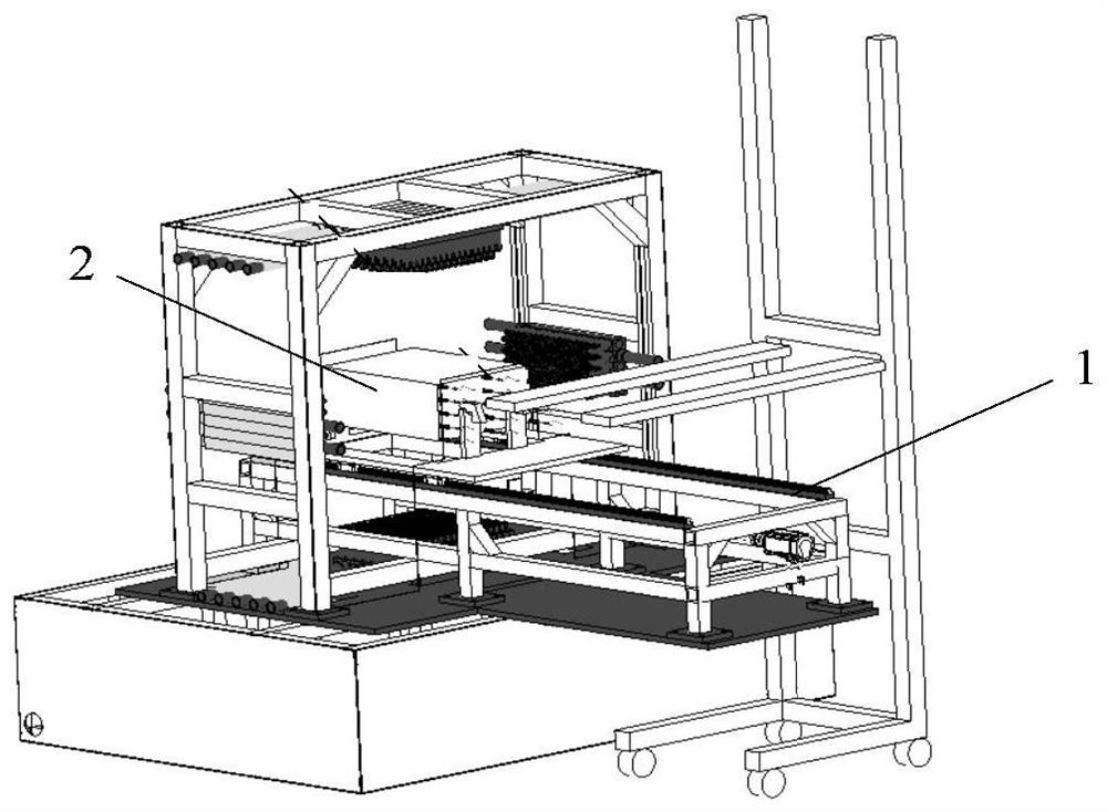
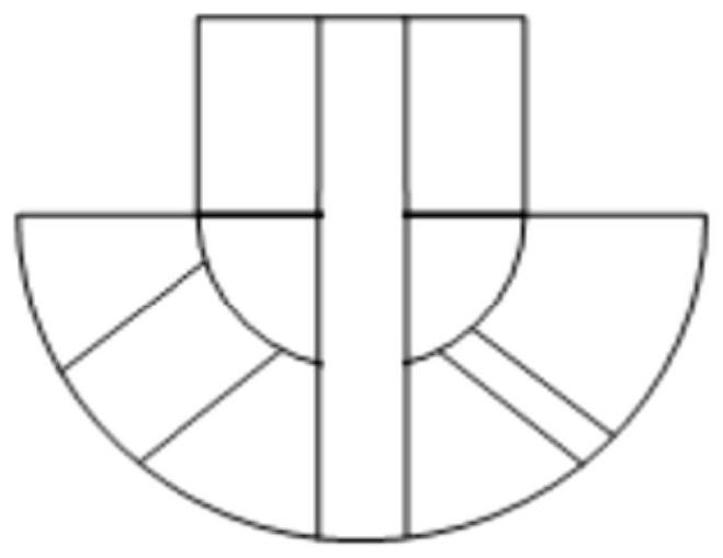
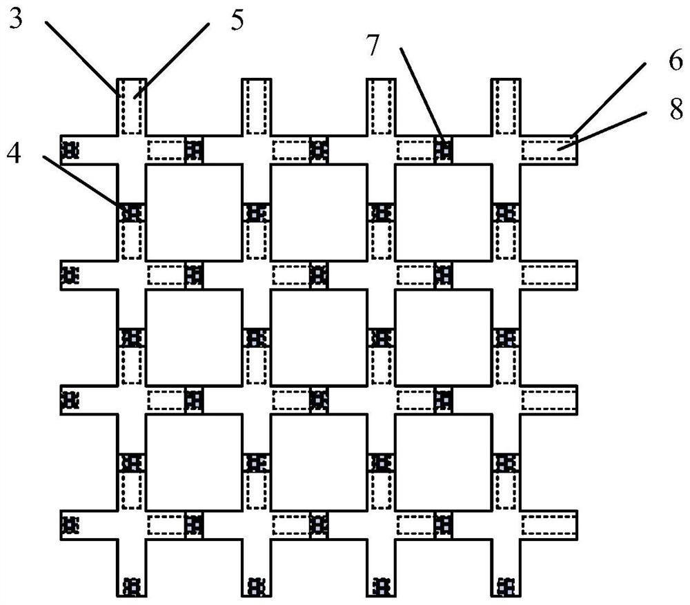

Image

  • Cooling system and cooling method for I-shaped steel
  • Cooling system and cooling method for I-shaped steel
  • Cooling system and cooling method for I-shaped steel

Examples


Embodiment 1

[0075] The size of the I-shaped steel of the present embodiment is 165mm * 165mm * 10000mm, and its composition by weight percentage (wt%), comprises: C 0.15, Si 0.30, Mn 1.50, Nb 0.012, P≤0.015% and S≤0.015%, The rest is Fe, wherein the carbon equivalent CEV≤0.4%.

[0076] In each cycle, the length of a single nozzle group in the air mist mode (that is, the cooling path length of the air mist cooling) is 7m, the number of nozzles in the nozzle group in the air mist mode is 210, and the single nozzle in the air cooling mode The length of the group (that is, the length of the air-cooled cooling path) is 3m, and the number of nozzles in the nozzle group in the air-cooled mode is 90; a total of 8 groups are arranged, wherein, the first nozzle group is an air mist cooling nozzle group, and the second The nozzle group is an air-cooled nozzle group, the third nozzle group is an air-cooled nozzle group, the fourth nozzle group is an air-cooled nozzle group, the fifth nozzle group is ...

Embodiment 2

[0080] The size of the I-shaped steel in this embodiment is 150mm×150mm×9000mm, and its composition is by weight percentage (wt%), including: C 0.18, Si 0.40, Mn 1.35, Nb 0.045, P≤0.015% and S≤0.015% , and the rest is Fe, wherein the carbon equivalent CEV≤0.4%.

[0081] In each cycle, the length of a single nozzle group in the aerosol mode (that is, the cooling path length of the aerosol cooling) is 5.5m, the number of nozzles in the nozzle group in the aerosol mode is 165, and the single nozzle group in the air-cooling mode The length of the nozzle group (i.e. the length of the air-cooled cooling path) is 2.5m, and the number of nozzles in the nozzle group in the air-cooled mode is 75; a total of 10 groups are arranged, wherein the first nozzle group is an air mist cooling nozzle group, The second nozzle group is air-cooled nozzle group, the third nozzle group is air-cooled nozzle group, the fourth nozzle group is air-cooled nozzle group, the fifth nozzle group is air-cooled ...


PUM

PropertyMeasurementUnit
yield strengthaaaaaaaaaa
tensile strengthaaaaaaaaaa
yield strengthaaaaaaaaaa

Abstract

The invention discloses an I-shaped steel cooling system and a cooling method, belongs to the technical field of I-shaped steel cooling processes, and solves the problem that the performance stability of finished products is influenced by poor section temperature uniformity of I-shaped steel in the prior art. The system comprises a nozzle assembly, the nozzle assembly comprises multiple groups of nozzles, the nozzles have an aerial fog mode and an air cooling mode, at least one group of nozzles is in the aerial fog mode, and the multiple groups of nozzles are at least located on one side of I-shaped steel. The method comprises the following steps that I-shaped steel sequentially passes through multiple sets of nozzles from the first set of nozzles to the last set of nozzles, water mist cooling and air cooling are alternately conducted on the I-shaped steel, and finally the target cooling temperature is achieved. The cooling system and the cooling method can be used for cooling the I-shaped steel.

Description

technical field [0001] The invention belongs to the technical field of I-shaped steel cooling technology, and in particular relates to a cooling system and a cooling method for I-shaped steel. Background technique [0002] With the rapid development of my country's national economy, the further development of my country's automobiles, high-speed trains, high-rise buildings, ships, aircraft, aerospace, precision instruments and machining and manufacturing equipment requires materials to achieve high-strength plasticization and high-strength toughness, and controlled rolling control Cold process is a necessary means to improve strong plasticization and toughening. [0003] For I-shaped steel, the controlled rolling and controlled cooling process can control different microstructures according to the requirements of different strength levels. [0004] The I-shaped steel is a special-shaped steel. During the cooling process, the temperature of the lower flange is usually higher ...

Claims


Application Information

Patent Timeline
Patent Type & Authority Applications(China)
IPC IPC(8): C21D9/00C21D11/00C21D6/00C22C38/02C22C38/04
CPCC21D9/0062C21D9/0068C21D11/005C21D6/005C21D6/008C22C38/02C22C38/04C21D2211/005C21D2211/009
Inventor 白宇王卫卫张宏亮肖金福
Owner CENT IRON & STEEL RES INST
Learn More