Liquid cooling radiators and server system

A radiator and liquid cooling technology, which is applied to indirect heat exchangers, heat exchanger shells, heat exchanger types, etc., can solve problems such as large temperature difference, reduced heat dissipation performance of water-cooled plates, and reduced overall heat dissipation performance of liquid-cooled radiators

Active Publication Date: 2019-05-10
CHAMP TECH OPTICAL FOSHAN
View PDF6 Cites 2 Cited by
  • Summary
  • Abstract
  • Description
  • Claims
  • Application Information

AI Technical Summary

Problems solved by technology

In a traditional liquid-cooled radiator, the water pump drives the coolant into the water-cooled plate, and then flows back from the water-cooled plate to the condenser for cooling and then returns to the water pump. The water-cooled plates are connected in series, and the temperature of the coolant flows through each water-cooled plate. As a result, the temperature difference between the first water-cooled plate and the last water-cooled plate is relatively large, and the heat dissipation performance of the water-cooled plates decreases in turn, resulting in a decrease in the overall heat dissipation performance of the liquid-cooled radiator

Method used


Image

  • Liquid cooling radiators and server system
  • Liquid cooling radiators and server system
  • Liquid cooling radiators and server system

Examples


Embodiment 1

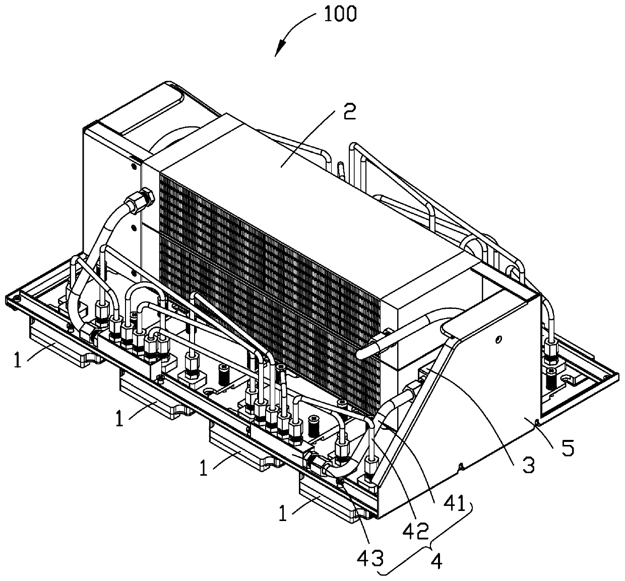
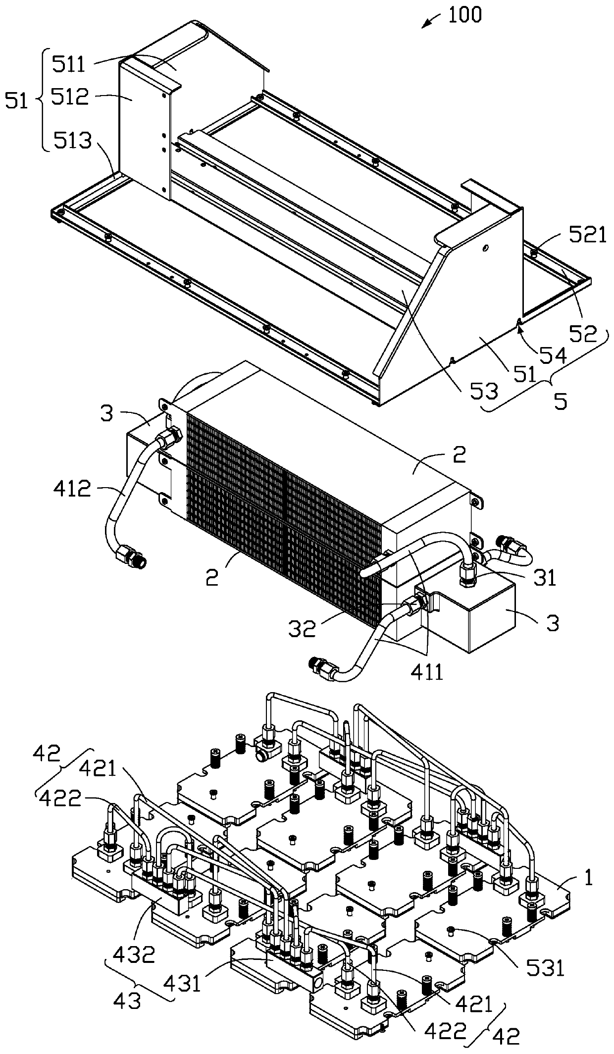
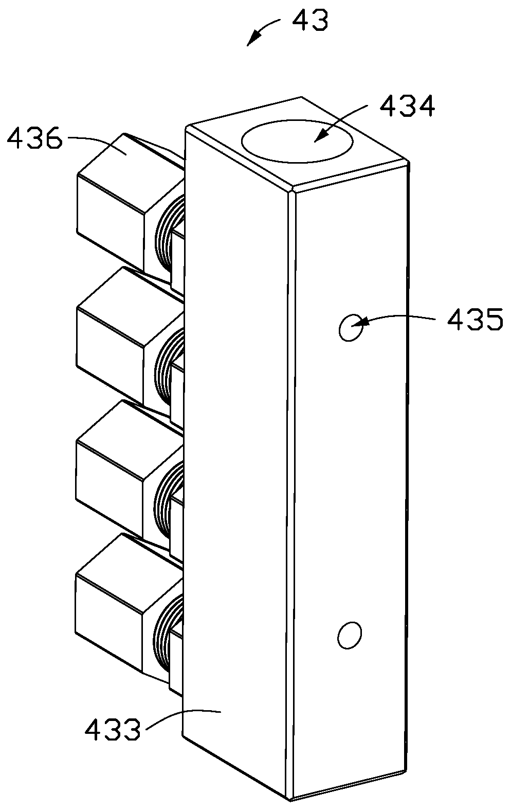
[0080] see figure 1 with Figure 9 , the server system 600 includes a plurality of electronic chips 61 , and the liquid cooling radiator 100 is used for dissipating heat from the plurality of electronic chips 61 in the server system 600 . The liquid cooling radiator 100 includes a plurality of water cooling plates 1 , a condenser 2 , a driver 3 , a cooling liquid pipe assembly 4 and a mounting bracket 5 . The plurality of water cooling plates 1 and the condenser 2 are fixedly arranged on the installation bracket 5 . The driver 3 is respectively connected to the plurality of water cooling plates 1 and the condenser 2 through the cooling liquid pipe assembly 4 . The cooling liquid pipeline assembly 4 includes a main pipeline 41 , branch pipelines 42 and distribution blocks 43 . The splitter block 43 is also fixedly arranged on the installation bracket 5 . The plurality of water cooling plates 1 are connected in parallel to the distribution block 43 through the branch pipe 42...

Embodiment 2

[0094] see Figure 7 with Figure 8 The liquid-cooled radiator 200 of the second embodiment is substantially the same as the liquid-cooled radiator 100 of the first embodiment, the difference is that the liquid-cooled radiator 200 of the second embodiment has a set of water-cooled plates 1A, a condenser 2A, a driver 3A and A set of coolant pipe assemblies 4A. The structure and function of the liquid cooling radiator 200 will not be repeated here.

[0095] It can be understood that in other embodiments, the number of water-cooled plate 1, condenser 2, driver 3 and coolant pipe assembly 4 can be increased or decreased in multiples according to the actual situation, and is not limited to the situation of embodiment 1 and embodiment 2 .

[0096] The liquid-cooled radiator 100 connects multiple water-cooled plates 1 to the condenser 2 in parallel, uses a driver 3 to provide power for multiple water-cooled plates 1, and sends cooling liquid of the same temperature to multiple wat...


PUM


Abstract

The invention discloses liquid cooling radiators. A liquid cooling radiator comprises a plurality of water cooling plates, condensers, drivers, cooling liquid pipeline assemblies and a mounting bracket. The plurality of water cooling plates and the condensers are fixedly set on the mounting bracket. The cooling liquid pipeline assemblies comprise main pipelines, shunt blocks and branch pipelines.The shunt blocks are also fixedly set on the mounting bracket. The plurality of water cooling plates are connected with the shunt blocks in parallel through utilization of the branch pipelines. The condensers, the drivers and the shunt blocks are connected through utilization of the main pipelines. The drivers are used for providing working power. Through utilization of the shunt blocks and the branch pipelines, cooling liquid in the condensers is shunted to the plurality of water cooling plates, then the cooling liquid flows back to the condensers for cooling through utilization of the branchpipelines, the shunt blocks and the main pipelines, and the condensers send the cooled cooling liquid to the drivers through utilization of the main pipelines, thereby forming a loop system.

Description

technical field [0001] The invention relates to the field of heat dissipation of electronic products, in particular to a liquid cooling radiator and a server system. Background technique [0002] With the rapid development of the electronics industry, the heat generated by electronic chips is increasing, and the requirements for heat dissipation performance are getting higher and higher. On a server system, space is limited and there are often multiple high-power and performance-critical chips that need to be cooled. In a traditional liquid-cooled radiator, the water pump drives the coolant into the water-cooled plate, and then flows back from the water-cooled plate to the condenser for cooling and then returns to the water pump. The water-cooled plates are connected in series, and the temperature of the coolant flows through each water-cooled plate. As a result, the temperature difference between the first water-cooled plate and the last water-cooled plate is relatively la...

Claims


Application Information

Patent Timeline
IPC IPC(8): H05K7/20
CPCF28D1/05366F28F1/126G06F1/20G06F2200/201H05K7/20809H05K7/20818F28F3/12F28F9/0253F28F2275/20H05K7/20318H05K7/20327
Inventor 符猛陈乔龙刘林蔚
Owner CHAMP TECH OPTICAL FOSHAN
Why Eureka
Try Eureka