Motor controller shell, motor controller and vehicle

A technology for motor controllers and casings, which is applied in the direction of casings/cabinets/drawer components, electrical equipment casings/cabinets/drawers, electrical components, etc., which can solve problems such as inability to achieve a good cooling effect, and achieve Guarantee the cooling effect and improve the cooling effect

Pending Publication Date: 2022-03-01
HYCET TRANSMISSION SYST (JIANGSU) CO LTD BAODING RES & DEV BRANCH
View PDF0 Cites 2 Cited by
  • Summary
  • Abstract
  • Description
  • Claims
  • Application Information

AI Technical Summary

Problems solved by technology

[0003] The motor is controlled by the motor controller to start and stop. The motor controller is provided with a cooling component, a first device and a second device. The cooling component can cool the first device and the second device in turn. However, the cooling component is in the After cooling the first device, the temperature of the water in the cooling unit will rise, and the second device will not be able to achieve a better cooling effect when the cooling unit with the increased water temperature is used to cool the second device

Method used


Image

  • Motor controller shell, motor controller and vehicle
  • Motor controller shell, motor controller and vehicle
  • Motor controller shell, motor controller and vehicle

Examples


Embodiment 1

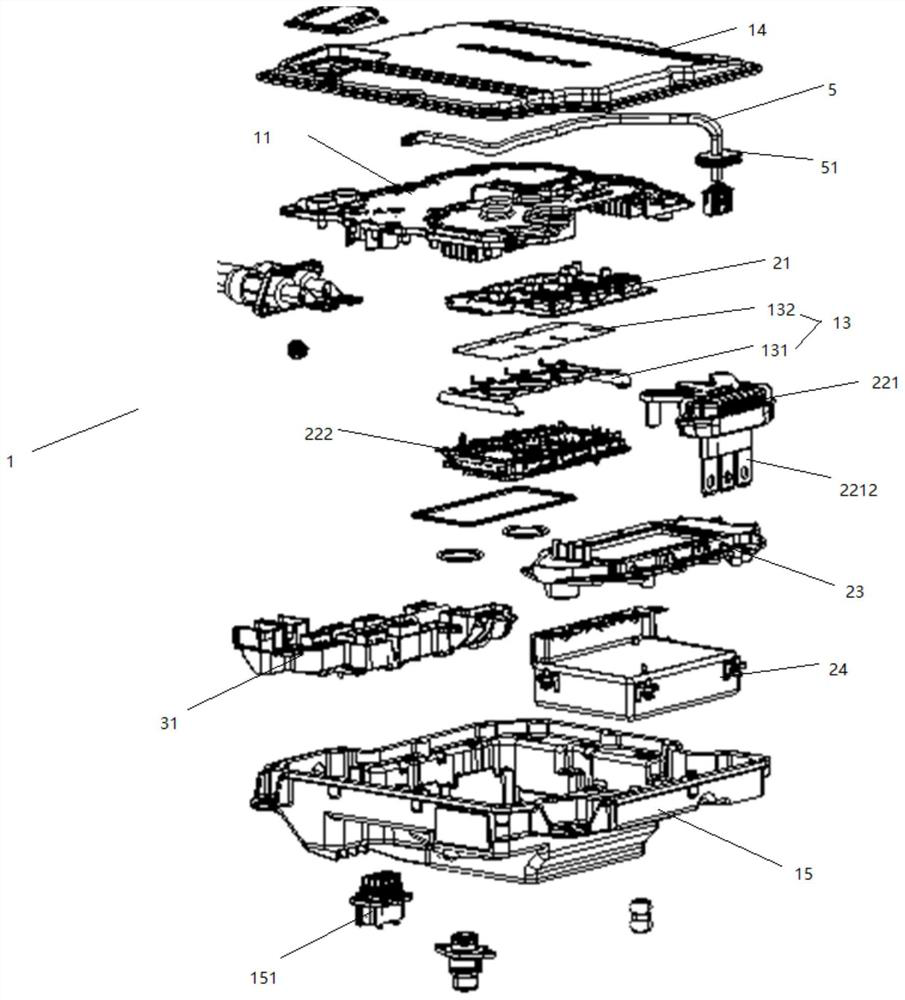
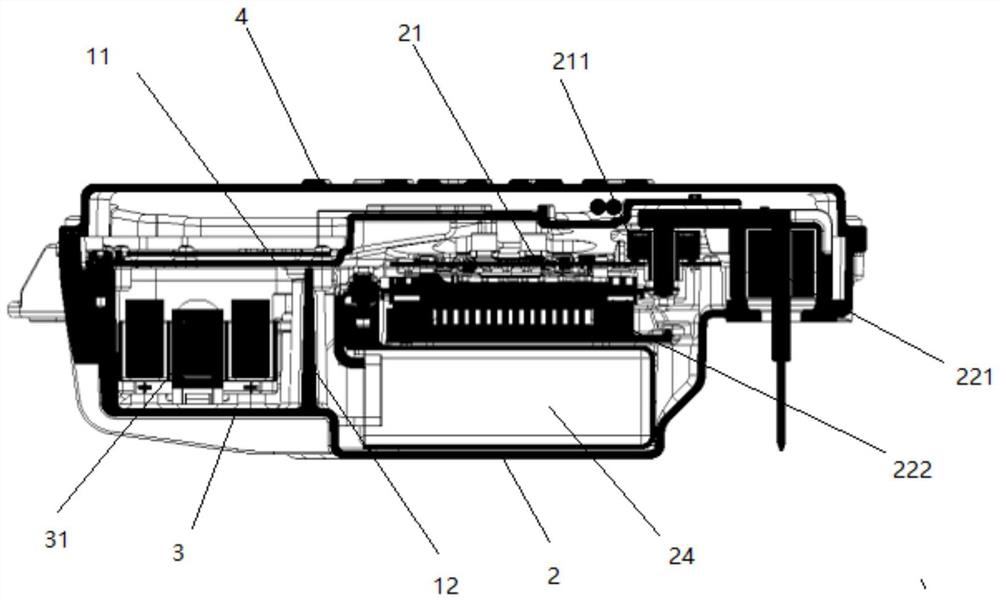
[0036] refer to figure 1 shows an exploded schematic diagram of a motor controller, refer to figure 2 An assembled cross-sectional view of a motor controller is shown. A motor controller housing, including a plurality of component placement slots, the plurality of component placement slots are used to place at least a first component and a second component; wherein, between the first component and the second component A cooling component 23 is provided; when the cooling fluid flows through the cooling component 23, it is used for cooling the first device and the second device at the same time.

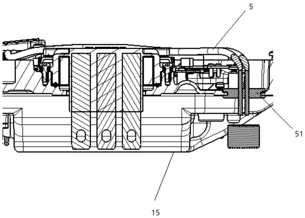
[0037] In the embodiment of this application, refer to figure 1 As shown, the motor controller housing 1 is provided with an upper cover 14 and a lower housing 15, the upper cover 14 and the lower housing 15 are both ends of the motor controller housing 1, and the lower housing 15 is provided with a high voltage connection device (not shown in the figure) and low-voltage connector ...

Embodiment 2

[0048] Based on the same inventive concept, another embodiment of the present application provides a motor controller, and the motor controller includes the motor controller housing provided in the first embodiment.

[0049] The first shielding plate 11 and the second shielding plate 12 divide the motor controller housing 1 into the first device placement slot 2, the second device placement slot 3 and the third device placement slot 4. Therefore, the embodiment of the present application will be different in the following The embodiment of the motor controller is described.

[0050] A second low-voltage component is arranged in the third device placement slot 4, and the second low-voltage component may include a control board (not shown in the figure).

[0051] The control board is the first core control part of the entire motor controller, and is mainly used to control the IGBT power output module 22 to realize the conversion between direct current and alternating current and...

Embodiment 3

[0100] Based on the same inventive concept, Embodiment 3 of the present application provides a vehicle. The vehicle is provided with a motor controller as provided in Embodiment 2, and the motor controller is provided with a motor controller housing as provided in Embodiment 1.


PUM


Abstract

The embodiment of the invention provides a motor controller shell, a motor controller and a vehicle, and belongs to the technical field of controllers. Comprising a plurality of device placing grooves which are at least used for placing a first device and a second device; wherein a cooling part is arranged between the first device and the second device; when cooling liquid circulates in the cooling part, the cooling part is used for cooling the first device and the second device at the same time. By using the motor controller shell, the motor controller and the vehicle provided by the invention, the cooling effect of the cooling component on the second device can be improved.

Description

technical field [0001] The embodiments of the present application relate to the technical field of controllers, and in particular, to a motor controller casing, a motor controller and a vehicle. Background technique [0002] With the development of the new energy vehicle market, the motor and electronic control, which are key components of pure electric vehicles, are highly valued by the industry, and higher requirements are placed on the cooling performance of the motor. [0003] The motor is controlled by the motor controller to start and stop. The motor controller is equipped with a cooling component, a first device and a second device. The cooling component can cool the first device and the second device in turn. However, the cooling component is in the After the first component is cooled, the temperature of the water in the cooling component will rise, and when the second component is cooled by the cooling component whose water temperature has risen, a better cooling ef...

Claims


Application Information

Patent Timeline
Patent Type & Authority Applications(China)
IPC IPC(8): H05K7/20H05K7/10H05K5/02H05K9/00H02G15/013
CPCH05K7/20218H05K7/10H05K5/0247H05K9/0022H02G15/013
Inventor 李森杨攀张骏飞罗贵恒
Owner HYCET TRANSMISSION SYST (JIANGSU) CO LTD BAODING RES & DEV BRANCH
Why Eureka
Try Eureka