Spin-orbit-type reciprocating piston compressor

A reciprocating piston and compressor technology, applied in the field of compressors, can solve problems such as monotonous layout, piston reciprocating motion law cannot be designed according to needs, and swash plate compressors are not suitable for large-displacement compressors, so as to increase flexibility and structure The effect of compactness and increased bearing capacity

Inactive Publication Date: 2010-02-10
ZHEJIANG HONGYOU AIR COMPRESSOR MFG
View PDF0 Cites 19 Cited by
  • Summary
  • Abstract
  • Description
  • Claims
  • Application Information

AI Technical Summary

Problems solved by technology

However, in the existing swash plate type reciprocating piston compressor, the working surface of the swash plate is flat, so there are three problems: firstly, the motion law of the swash plate is determined by the angle between the swash plate working surface and the rotating shaft; It is decided, in other words, the reciprocating motion of the piston cannot be designed according to the needs. For example, in the early stage of the compression stroke, it is hoped that the piston will move slightly faster, and the piston should be controlled to move slower during the exhaust period in the later stage, so as to reduce the compressor. The second is that the structure of the swash plate determines that it can only adopt an outstretched structure relative to the rotor, that is, the swash plate surrounds the rotor in the radial and circumferential directions, so the layout is monotonous; finally, the swash plate structure can only adopt a single Due to the limited load, the swash plate compressor is usually not suitable for large displacement compressors

Method used


Image

  • Spin-orbit-type reciprocating piston compressor
  • Spin-orbit-type reciprocating piston compressor
  • Spin-orbit-type reciprocating piston compressor

Examples


Embodiment Construction

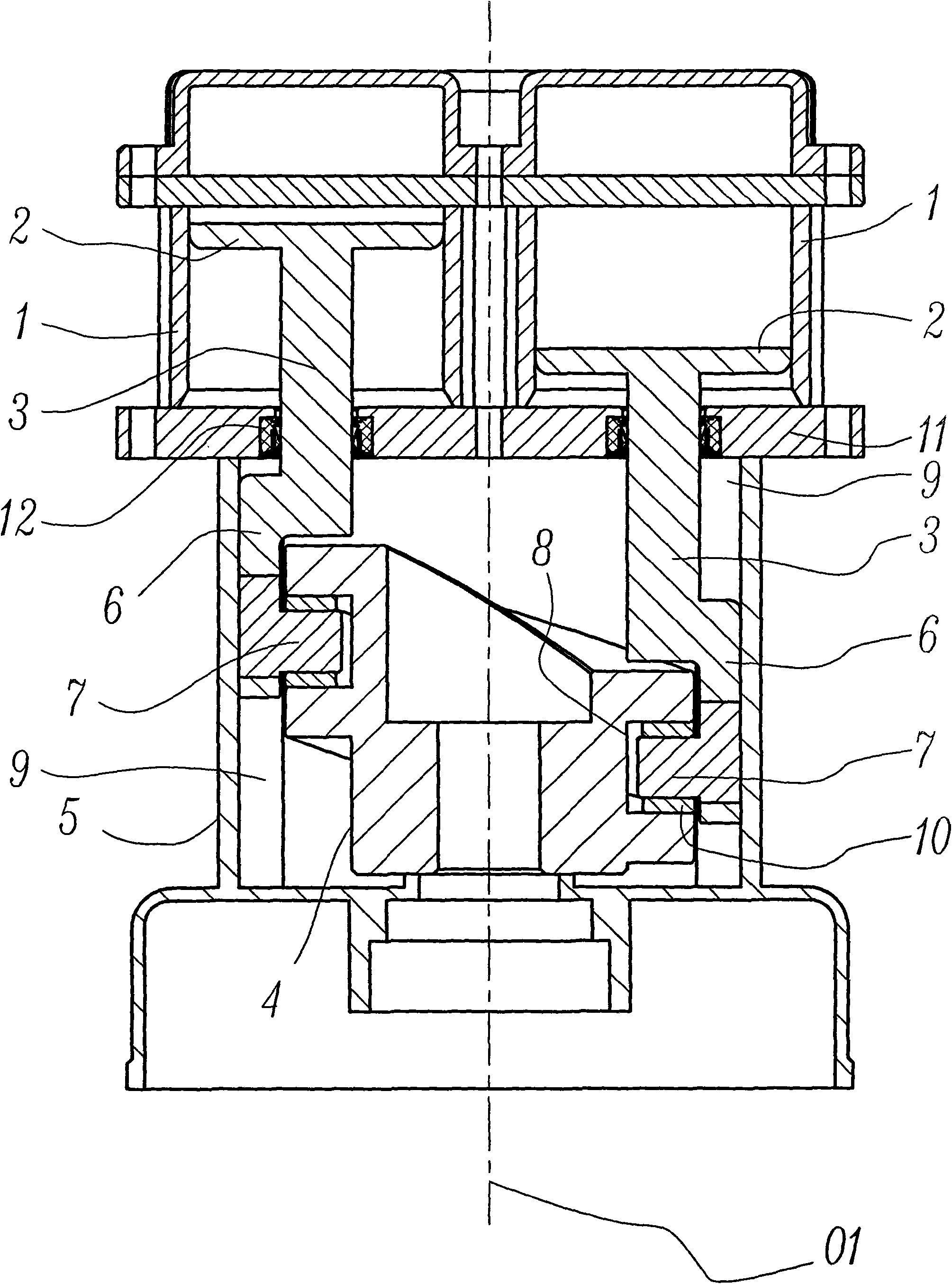
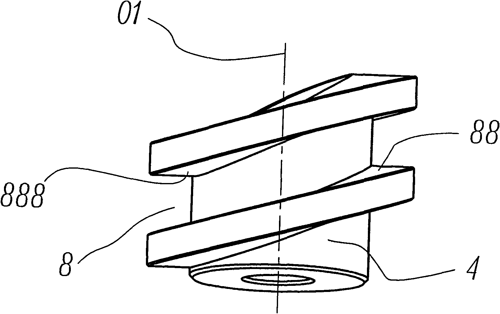
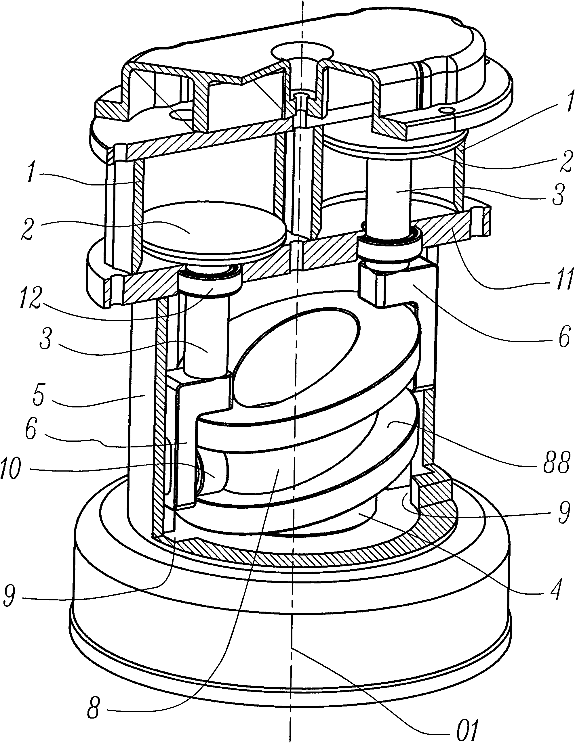
[0033] The present invention will be further described below with specific embodiment, see Figure 1-8 :

[0034] A rotary rail type reciprocating piston compressor, including a cylinder 1, a piston 2, a connecting rod 3, a rotor 4, a sliding seat 5, several sliders 6 and several thrust pins 7, the rotor 4 is driven by a motor, etc. The motor is driven to rotate, and a rotary rail 8 is provided on the rotor 4, and a working surface 88 is provided on the rotary rail 8; several slide rails 9 are provided on the slide seat 5, and all the slide rails 9 are straight. The concave rail (as shown in the figure) or convex rail (not shown in the figure) is arranged parallel to the axis O1 of the rotor 4, and the cross-sectional shape of the slide rail 9 can be a rectangular notch shape, a circular arc notch shape, or a triangular notch shape or trapezoidal notch shaped etc., like Figure 7 What is shown is a rectangular notch-shaped concave rail-shaped slide rail, which is shaped like...


PUM


Abstract

The invention belongs to the technical field of a compressor, and more particularly relates to a spin-orbit-type reciprocating piston compressor which comprises an air cylinder, a piston and a connecting rod, and is characterized by being provided with a rotor, a sliding seat, a plurality of sliding blocks and thrust pins; wherein the rotor is provided with a spin orbit, the sliding seat is provided with a plurality of sliding rails parallel to the axes of the rotor, the sliding blocks are matched with the sliding rails in a sliding or rolling way, one end of the thrust pins is connected withthe sliding blocks, and the thrust pins move along the sliding rails together with the sliding blocks; the other end or middle end of the thrust pins can be matched with the spin orbit and correspondingly driven to move along the work molded surface of the spin orbit; one end of the connecting rod is connected with the piston, and the other end thereof is connected with the sliding blocks; as thespin-orbit structure is adopted to realize the reciprocating motion of the piston, a crankshaft and connecting rod mechanism of the traditional compressor can be eliminated, the spin-orbit-type reciprocating piston compressor carries forward the advantage of compact structure of a swash plate compressor, and is flexible in layout, so as to further realize the design of large delivery capacity of the compressor, and more importantly control the reciprocating motion law of the piston.

Description

technical field [0001] The invention belongs to the technical field of compressors, and relates to a reciprocating piston compressor, in particular to a rotary rail type reciprocating piston compressor. Background technique [0002] The use history of reciprocating piston compressor is very long, its application is very extensive, it is the main model of compressor at present. It is a well-known fact that reciprocating piston compressors generally use a crank-connecting rod mechanism to achieve power and motion conversion. Because the connecting rods and crankshafts involved are not only large in size, but also need to be equipped with special balance weights to balance the crankshaft and connecting rod. The centrifugal inertial force generated by the large end of the rod is the main reason why the structure of the traditional crank-connecting rod reciprocating piston compressor is not compact enough. In view of this, an extremely compact swash plate reciprocating piston co...

Claims


Application Information

Patent Timeline
Patent Type & Authority Applications(China)
IPC IPC(8): F04B35/01F04B39/00
CPCF04B35/01
Inventor 陈君立耿爱农阮勤江李辛沫
Owner ZHEJIANG HONGYOU AIR COMPRESSOR MFG
Why Eureka
Try Eureka