Electric valve

A technology of electric valve and valve port, which is applied in the direction of valve lift, valve details, valve device, etc., which can solve the problems such as the deviation of the stop mechanism, and achieve the effect of reducing the number of parts, reducing the deviation, and stabilizing the stop position

Active Publication Date: 2010-02-10
SAGINOMIYA SEISAKUSHO INC
View PDF1 Cites 25 Cited by
  • Summary
  • Abstract
  • Description
  • Claims
  • Application Information

AI Technical Summary

Problems solved by technology

In addition, on the shaft of the electric valve, there are problems such as that the stop mechanism is prone to deviation.

Method used


Image

  • Electric valve
  • Electric valve
  • Electric valve

Examples


Embodiment Construction

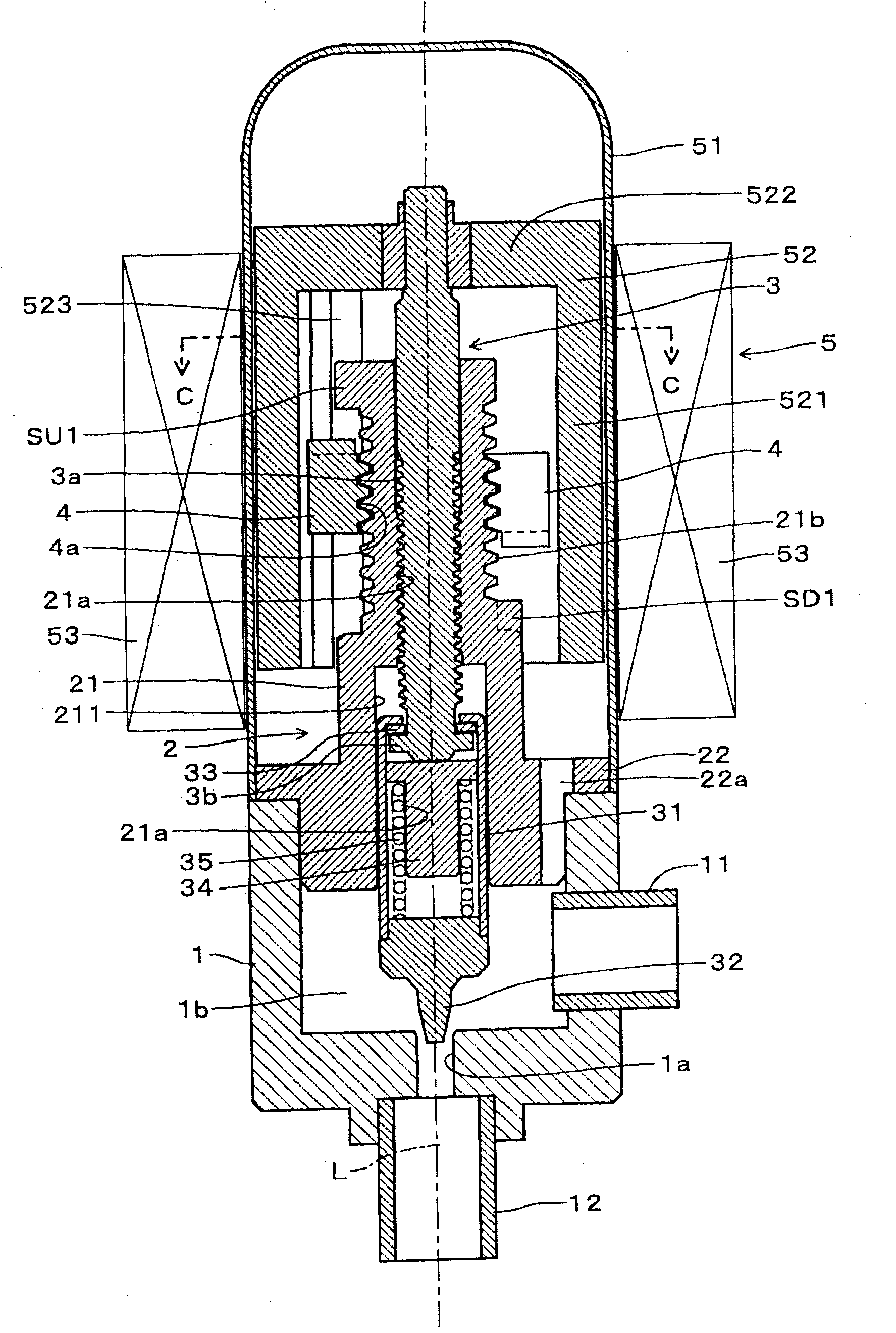
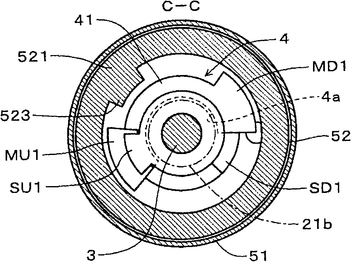
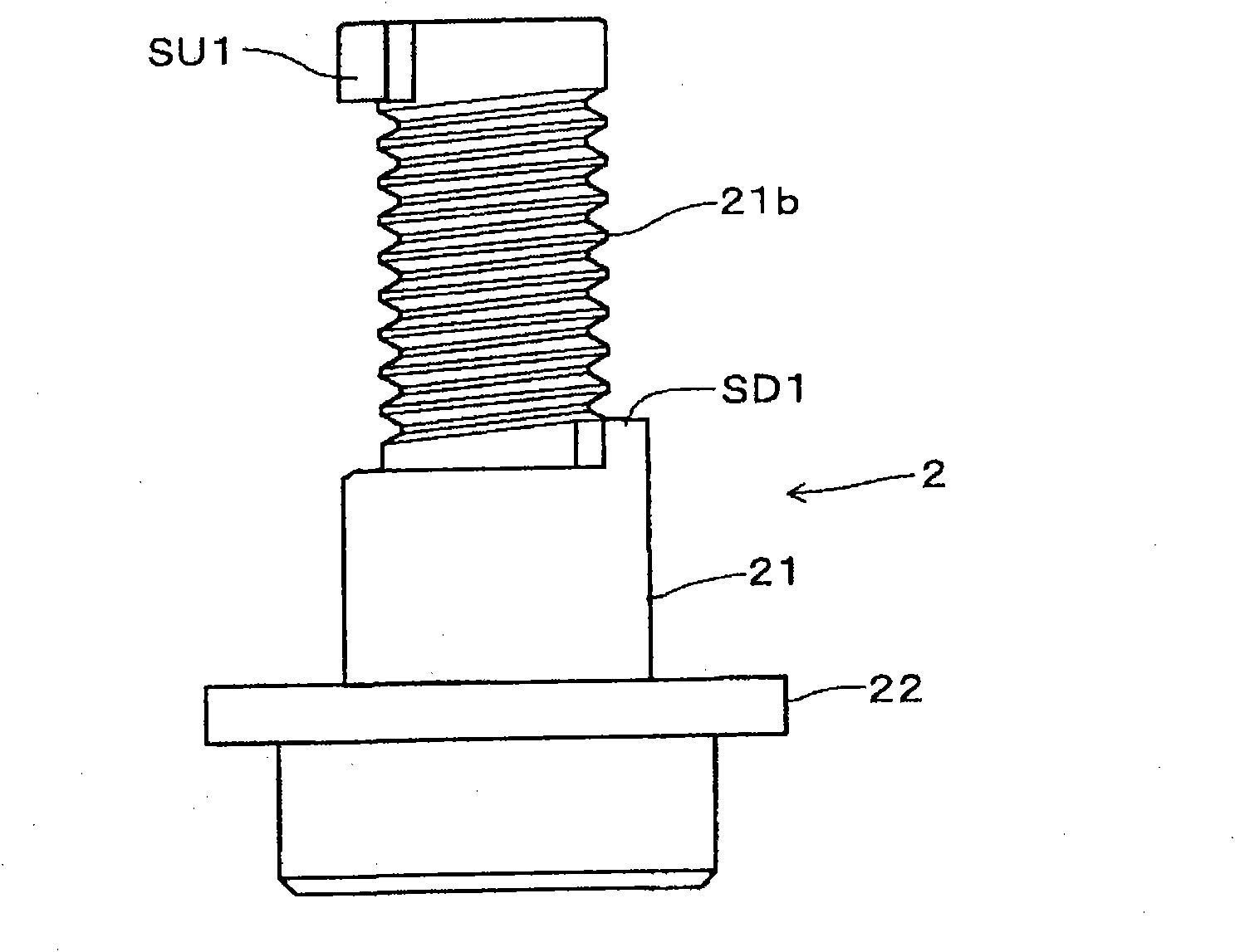
[0035] Embodiments of the electric valve of the present invention will be described below with reference to the drawings. In addition, in each of the following embodiments and modifications, the same elements as those in the first embodiment and corresponding elements are attached with the same symbols, and redundant detailed descriptions are omitted. figure 1 is a longitudinal sectional view of the electric valve of the first embodiment, figure 2 yes figure 1 C-C cutaway view, image 3 It is the side view of the appearance of the supporting part of the electric valve, Figure 4 It is the top view and longitudinal sectional view of the driven slider of the electric valve. In addition, the concept of "up and down" in the following explanations is the same as figure 1 The upper and lower correspondences in . This electric valve has a cylindrical valve body 1 . In the valve main body 1, a valve port 1a is opened at one end thereof. Moreover, the support member 2 is attach...


PUM


Abstract

In an electric valve of the invention, the number of components of a motion limiting mechanism relatively to a rotor shaft (3) and a magnetic rotor (52) is reduced, and the precision is increased. Theguiding external thread (21b) is integrated with a bracket part at the periphery of the bracket part (21) of the bracket component (2). A driven slider (4) of a guiding internal thread (4a) which isscrewed with one part on the periphery of the guiding external thread is provided. A projection strip (523) is provided at the inner periphery of the magnetic rotor. A fixed lower end limiter (SD1) isintegrated with the bracket part at the lower end of the guiding external thread. A fixed upper end limiter (SU1) is integrated with the bracket part at the upper end of the guiding external thread.The driven slider is formed by the synthetic resin which is taken as the elastic component. When the magnetic rotor rotates, the projection strip is used for rotating the driven slider and abutting against the fixed lower end limiter or the fixed upper end limiter thereby restraining the lower position and upper position.

Description

technical field [0001] The present invention relates to an electric valve for controlling the flow rate of refrigerant, such as an expansion valve of a refrigeration cycle. Background technique [0002] Conventionally, in the refrigeration cycle, an expansion valve is installed between the outdoor heat exchanger and the indoor heat exchanger. In the cooling mode, the refrigerant from the outdoor heat exchanger is expanded by the expansion valve and guided to the indoor heat exchanger. ; In the heating mode, the refrigerant from the indoor heat exchanger is expanded by the expansion valve and then directed to the outdoor heat exchanger. As such an expansion valve, various methods of controlling the flow rate of the refrigerant have been proposed in order to cope with normal operation, defrosting operation, dehumidification operation, and the like. [0003] Such an electric valve is equipped with a stopper mechanism to limit the valve position of the maximum opening degree of...

Claims


Application Information

Patent Timeline
Patent Type & Authority Applications(China)
IPC IPC(8): F16K1/02F16K1/52F16K31/06
Inventor 平川尚中野诚一
Owner SAGINOMIYA SEISAKUSHO INC
Why Eureka
Try Eureka