Method of and apparatus for controlling the temperature of a fluidized bed reactor

A fluidized bed reactor and equipment technology, applied in fluidized bed combustion equipment, chemical instruments and methods, steam generation methods using heat carriers, etc., can solve the problems of reducing oil production and undesired chemical reactions, etc.

Inactive Publication Date: 2010-02-10
A AHLSTROM CORP
View PDF3 Cites 1 Cited by
  • Summary
  • Abstract
  • Description
  • Claims
  • Application Information

AI Technical Summary

Problems solved by technology

Thus, fluidization of the bed material in a fluidized bed pyrolyzer produces a relatively uniform and stable process temperature, but in some instances it has been noted that a portion of the fuel in a fluidized bed pyrolyzer The reaction does not take place at the solution temperature, which leads to undesired chemical reactions and, for example, to reduced oil yields

Method used


Image

  • Method of and apparatus for controlling the temperature of a fluidized bed reactor

Examples


Embodiment Construction

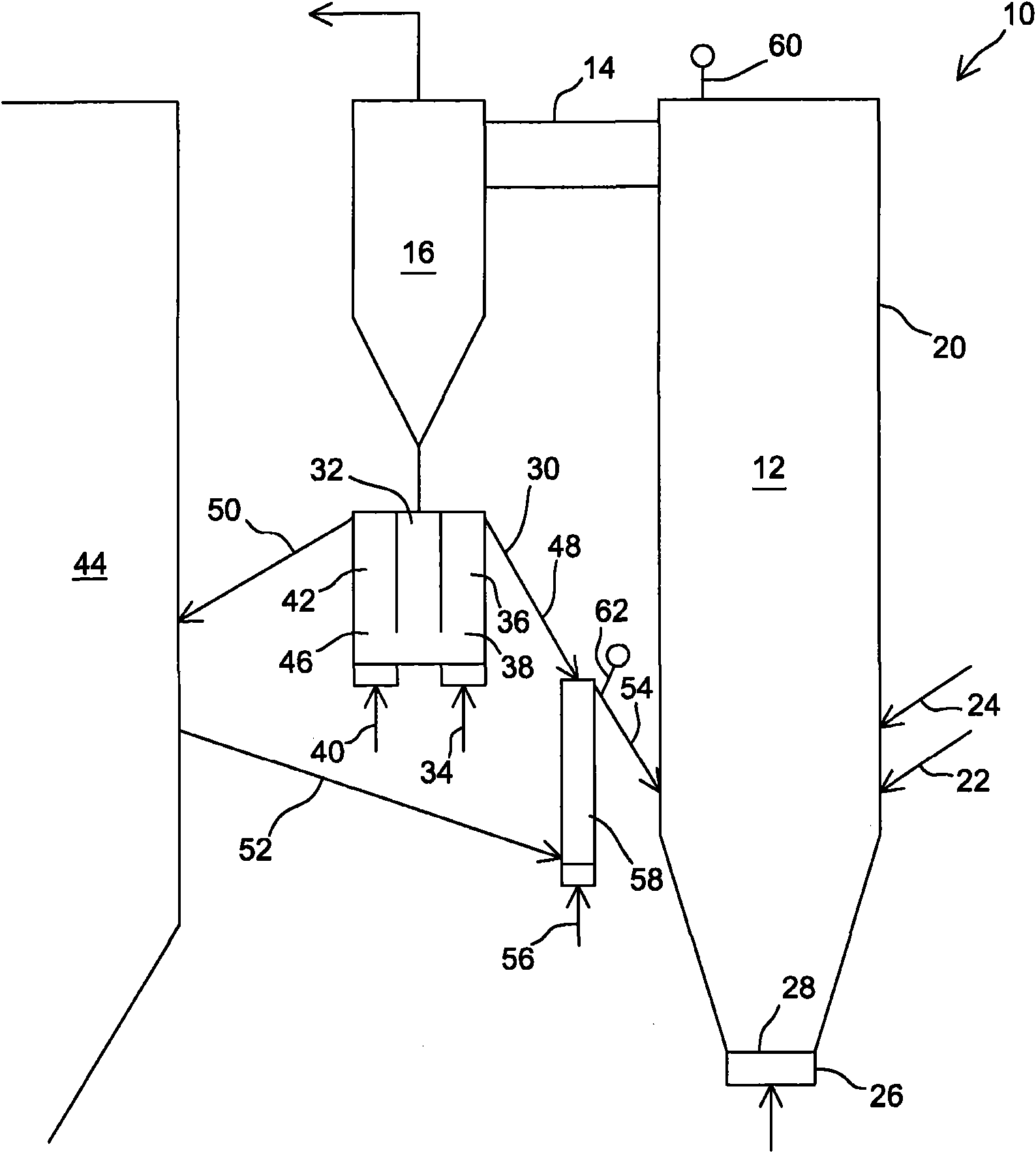
[0027] figure 1 Shown is a circulating fluidized bed pyrolyzer 10 according to a preferred embodiment of the present invention, said fluidized bed pyrolyzer comprising a reaction chamber 12, a gas discharge conduit 14 connected to the upper part of the reaction chamber and connected to Particle separator 16 to conduit 14 . Solid particles, in particular coke particles, are separated from the pyrolysis gas by means of a particle separator 16 . From the particle separator the pyrolysis gas is directed through a filter to a gas cooler ( figure 1 not shown in ), in which the pyrolysis oil is condensed from the pyrolysis gas. The uncondensed gaseous products are directed from the gas cooler for other uses, for example to be combusted or used as fluidization gas for a pyrolyzer. Conventional conduits 22, 24 are connected to the side wall 20 of the reaction chamber 12, for example to conduct fuel and inert bed material. Also arranged below the reaction chamber is a wind box 26 fo...


PUM


Abstract

Method of and apparatus for controlling the temperature of a fluidized bed reactor (10), comprising separator means (16) for separating first solid particles from the fluidized bed reactor; a return duct (30) for returning a first portion of the first solid particles to the fluidized bed reactor; a discharge duct (50) for the discharge of a second portion of the first solid particles and an inletduct (52) for transferring second solid particles from a second fluidized bed reactor to said fluidized bed reactor, in which the return duct (30) and the inlet duct (52) share a common end 10 portion (54) for transferring a mixture of solid particles, formed of the first portion of the first solid particles and the second solid particles, to the fluidized bed reactor (10). Said apparatus also preferably comprises a fluidized mixing device (58) for mixing the first portion of the solid particles and the second solid particles with each other.

Description

technical field [0001] The invention relates to a method and a device for controlling the temperature of a fluidized bed reactor arranged in connection with a second fluidized bed reactor according to the preambles of the independent claims. [0002] Accordingly, the present invention relates in particular to an apparatus comprising separator means for separating first solid particles from a fluidized bed reactor; for returning a first portion of said first solid particles to said flow a return conduit for a fluidized bed reactor; a discharge conduit for removing a second portion of said first solid particles; and for transferring a second solid particle from a second fluidized bed reactor to said fluidized bed reactor the inlet conduit. Further, the present invention inter alia relates to a method wherein first solid particles are separated from said fluidized bed reactor; a first portion of said first solid particles are conveyed back to said fluidized bed reactor along a r...

Claims


Application Information

Patent Timeline
Patent Type & Authority Applications(China)
IPC IPC(8): B01J8/00B01J8/26B01J8/38
CPCF23C10/10B01J2208/00061F23C10/005B01J8/26B01J8/388B01J8/0015F23C10/28B01J2208/00548C10B49/22F23C2900/10005B01J2208/00292B01J8/0055Y02E50/14Y02E50/10F23C10/04F23C10/32B01J8/38F22B1/02
Inventor M·伊塔佩尔托
Owner A AHLSTROM CORP
Why Eureka
Try Eureka