
Continuous casting mold with coolant channel

A continuous casting crystallizer and coolant technology, which is applied in the field of continuous casting crystallizers, can solve the problems of low share, etc., and achieve the effects of improved heat transfer, increased life, and high heat flux

Inactive Publication Date: 2012-06-13
SMS DEMAG AG
View PDF12 Cites 0 Cited by
  • Summary
  • Abstract
  • Description
  • Claims
  • Application Information

AI Technical Summary

Problems solved by technology

A major disadvantage of conventional cooling methods is the directed eddy currents, which have a major proportion in the axial direction of flow and a lower proportion in the radial direction of flow

Method used


Image

  • Continuous casting mold with coolant channel
  • Continuous casting mold with coolant channel
  • Continuous casting mold with coolant channel

Examples


Embodiment Construction

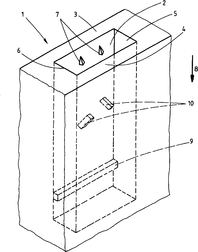
[0020] figure 1 Shown is a spatial representation of a part of a continuous casting mold 1 with a coolant channel 2 consisting of an inner mold wall 3 facing the molten metal on one side as the hot side and a mold side as the cold side The outer wall 4 is formed by a right side wall 5 and a left side wall 6 .

[0021] Swirl-generating elements 7 , 9 and 10 are arranged in flow direction 8 on inner mold wall 3 , ie on the hot side, and protrude into coolant channels 2 .

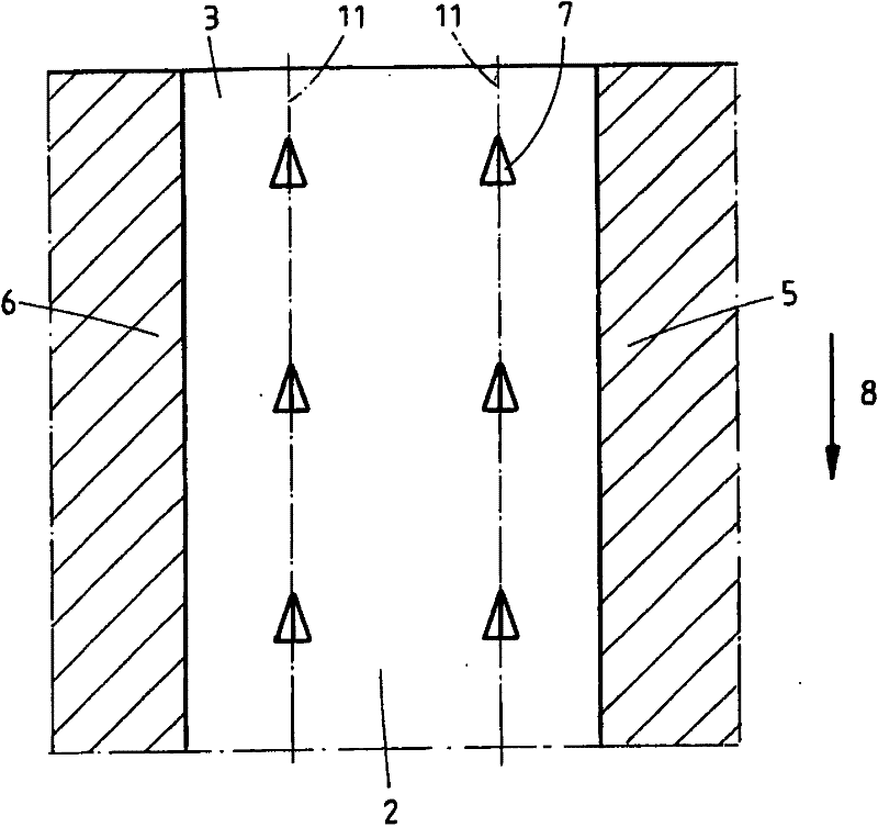
[0022] figure 2 A cutaway front view of the coolant channel 2 is shown, in which the tetrahedral vortex-generating elements 7 are arranged in two rows 11 on the mold inner wall 3 . The tetrahedrons point with their tips in the opposite direction to the flow direction 8 . With this arrangement, a progressive resistance is produced. Behind the tetrahedron the coolant is in a vortex. The tetrahedrons can also be arranged in a staggered manner.

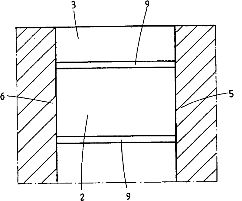
[0023] image 3 The vortex-generating elements 9 in the form...


PUM


Abstract

The invention relates to a continuous casting die (1) with a coolant channel (2), which is formed by an inner wall of the die (3) as the hot side, the wall facing the molten metal, an outer wall of the die (4) as the cold side, and a right side wall (5) and a left side wall (6). The coolant channel (2) is provided with turbulence-creating elements (7, 9, 10).

Description

technical field [0001] The invention relates to a continuous casting mold with a coolant channel consisting of an inner mold wall as the hot side facing the molten metal, an outer mold wall as the cold side, and a right-hand side and a left-hand side side wall composition. Background technique [0002] From DE 19826522 A1 a mold wall of a continuous casting mold is disclosed, which consists of a mold inner plate and a water tank connected to the mold inner plate by a screw connection, wherein the crystallizer On its side facing the water tank, the inner plate has webs, which in turn have grooves extending between them, in which grooves the filler is arranged. The grooves serve here as cooling channels for a cooling liquid, usually water. The filler serves to reduce the cross section of the channel, thereby increasing the flow speed of the cooling liquid in the cooling channel. [0003] DE 19842674A1 describes a similar filler. [0004] Furthermore, continuous casting mol...

Claims


Application Information

Patent Timeline
Patent Type & Authority Patents(China)
IPC IPC(8): B22D11/04B22D11/055
CPCB22D11/055B22D11/04
Inventor H·-J·奥登萨尔N·沃格尔
Owner SMS DEMAG AG
Learn More