
Plunger for holding and moving electrical components in particular ic's

An electronic device and plunger technology, which is applied in electrical components, electronic circuit testing, single semiconductor device testing, etc., can solve the problems of complex structure of head components, achieve small structure size, eliminate heat loss, and achieve the effect of temperature regulation

Inactive Publication Date: 2010-02-10
马尔帝电子系统有限公司
View PDF1 Cites 2 Cited by
  • Summary
  • Abstract
  • Description
  • Claims
  • Application Information

AI Technical Summary

Problems solved by technology

The disadvantage here, however, is that the construction of the head part is complex and requires a larger-sized contact plate with built-in fluid channels and corresponding fittings for the fluid connection lines
This header is not suitable for very small devices

Method used


Image

  • Plunger for holding and moving electrical components in particular ic's
  • Plunger for holding and moving electrical components in particular ic's
  • Plunger for holding and moving electrical components in particular ic's

Examples


Embodiment Construction

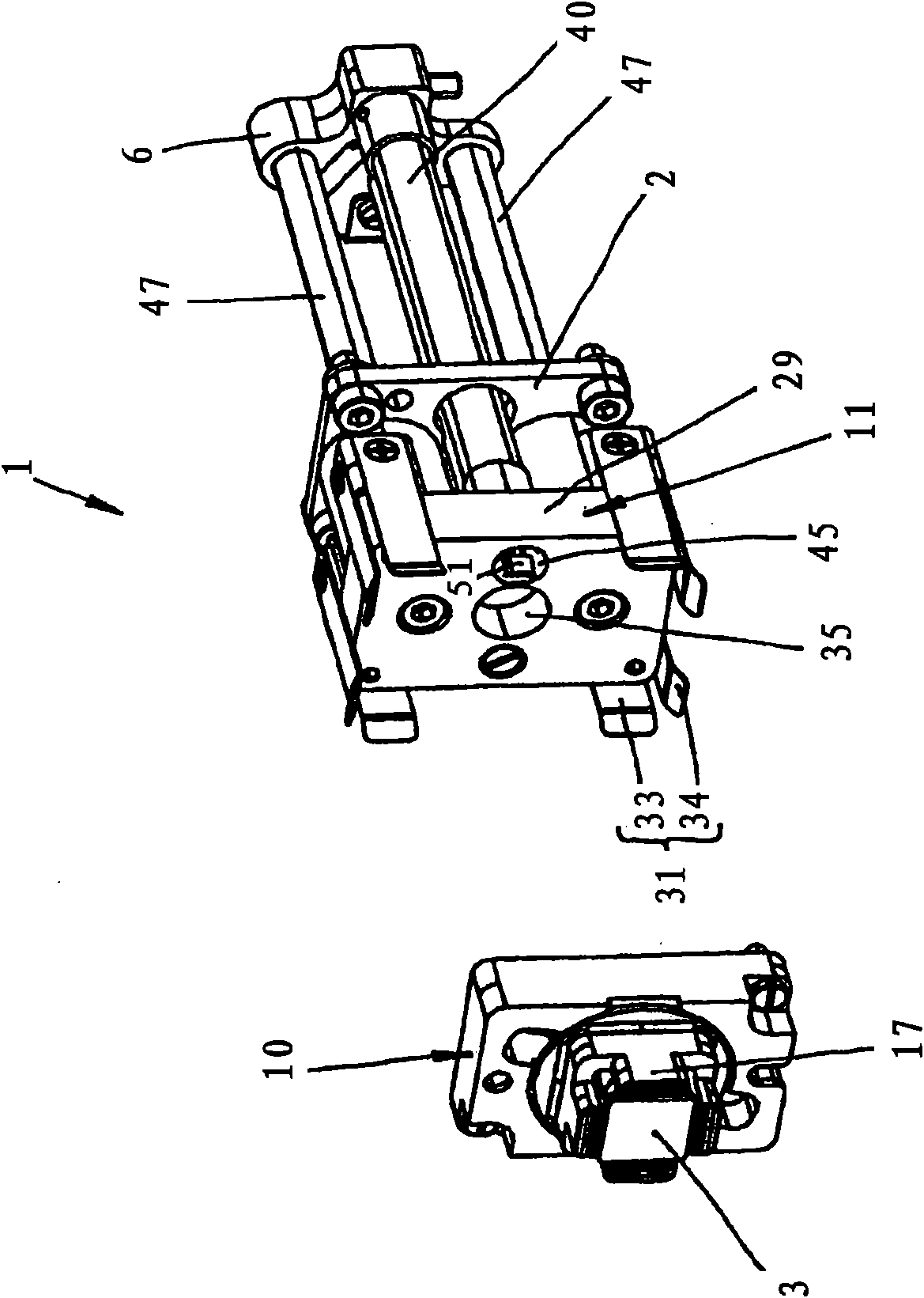
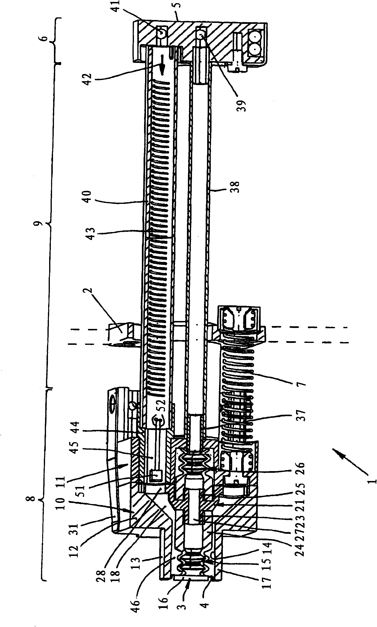
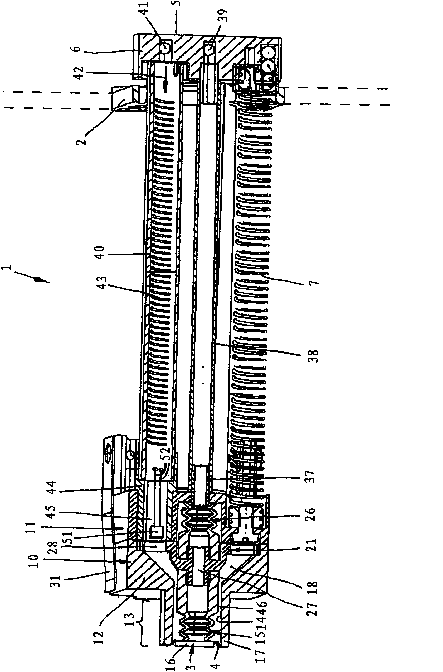
[0031] Depend on Figures 1 to 3 The plunger 1 can be seen, which is guided longitudinally displaceably on a plunger guide 2 . The plunger guide 2 can be fastened in a manner not shown, for example, on a circular carriage or a swinging device, by means of which the plunger 1 with the electronic components to be tested placed on the plunger 1 3 Move to a position where plunger 1 can move linearly (in figure 2 with 3 Middle left) to the contact position, in this position, each connecting leg 4 (pins) of the device 3 (see Figure 11 ) are placed on corresponding, not shown connecting contacts of a contact device (contact socket). The plunger 1 is therefore a holding device for the holding device 3, which can be piston-like in the figure 2 The retracted position shown in the image 3 Move back and forth between the previous positions shown in . The forward movement here is effected by a feed device (not shown) which presses against the rear face 5 of the rear end section 6...


PUM


Abstract

The invention relates to a plunger for holding and moving electrical components in particular IC's to and from a contacting device connected to a test bed, comprising a head piece (10) with a fluid distribution chamber (18) through which temperature-controlled fluid flows and in which a suction head (15) is arranged such that the temperature-controlled fluid flows around the suction head (15) andis diverted along the suction head (15) to the component (3).

Description

technical field [0001] The invention relates to a plunger for holding and moving electronic components, in particular for delivering IC's (Integrated Circuits) to and moving away from a contact device connected to a test device, as stated in the preamble of claim 1 The plunger of the contact device. Background technique [0002] The functionality of electronic devices, such as IC's (semiconductor devices having integrated circuits), is generally verified before they are mounted on circuit boards or otherwise used. The component to be tested is brought into contact hereby by an automatic handling device generally called a "handler" with a contact device, which is designed in particular as a contact socket and which is electrically connected to a test head of the test device. After the test process is completed, the components are removed from the contact device again by the operator and sorted according to the test results. [0003] In order to hold and switch on the compon...

Claims


Application Information

Patent Timeline
Patent Type & Authority Applications(China)
IPC IPC(8): G01R31/28
CPCG01R31/2874G01R31/26H01L22/00H01L21/67
Inventor M·绍勒S·蒂尔F·皮希尔G·耶泽尔A·维斯伯克A·鲍尔
Owner 马尔帝电子系统有限公司
Learn More