Vertical type ground hinge mechanism

A ground hinge and hinge technology, used in building structures, door/window fittings, buildings, etc., can solve the problems of low bearing capacity, easily damaged parts, complex structure, etc., and achieve large bearing capacity, accurate and stable positioning, and simple structure. Effect

Inactive Publication Date: 2010-02-17
秦中银
View PDF1 Cites 11 Cited by
  • Summary
  • Abstract
  • Description
  • Claims
  • Application Information

AI Technical Summary

Problems solved by technology

[0003] The present invention provides a vertical hinge mechanism, which solves the disadvantages of the above-mentioned "ground hinge" such as complex structure, easy damage to parts, and low bearing capacity.

Method used


Image

  • Vertical type ground hinge mechanism
  • Vertical type ground hinge mechanism
  • Vertical type ground hinge mechanism

Examples


Embodiment 1

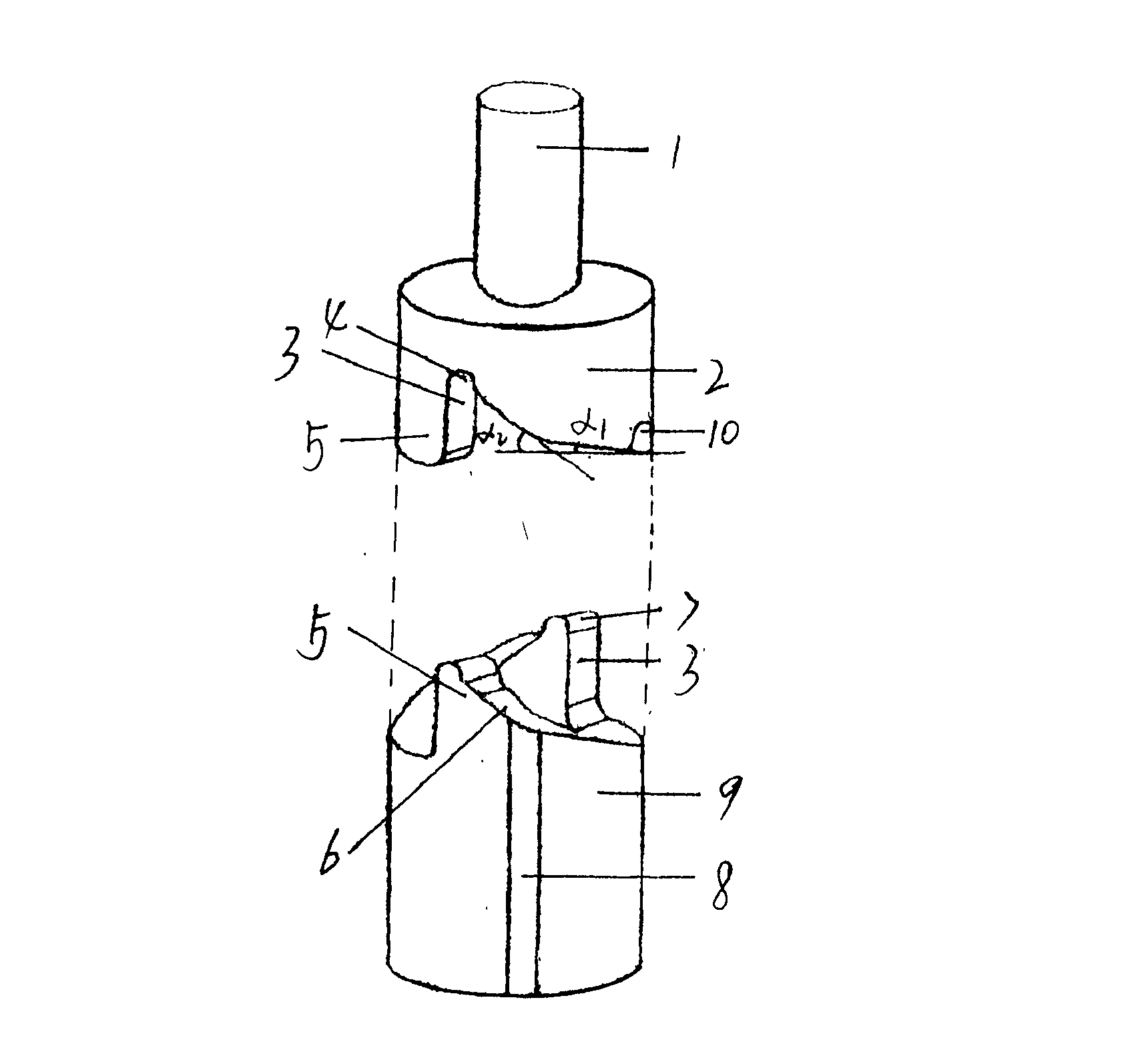
[0016] Such as figure 1 As shown, the vertical hinge mechanism of the present invention is composed of an upper hinge 2 and a lower hinge 9, and the meshing surfaces 6 of the upper hinge 2 and the lower hinge 9 are respectively provided with two symmetrical annular meshing teeth 5, and the meshing teeth 5 The engaging surface 6 is a helical surface (helix angle a=a 1 =a 2 =25°), the end face of one side of the meshing tooth 5 is an upright stop surface 3, so that the upper and lower hinges (doors and windows) can only be opened in one direction, and automatically reset within 180°; the end face of the upper hinge 2 is provided with a fixed shaft 1 , the body of the lower hinge 9 is provided with a keyway 8; the meshing teeth 5 are respectively provided with a raised semicircular U-shaped positioning tooth 7, and the corresponding upper hinge tooth root is set as a recessed semicircular U-shaped door closing stop positioning groove 4. There is a door opening angle positioning...

Embodiment 2

[0019] On the basis of Embodiment 1, the helix angle of the meshing surface 6 of the upper hinge 2 and the lower hinge 9 adopts a two-stage structure, that is, the helix angle is respectively: a 1 = 15°, a 2 = 32°. When the door is opened, the principle is the same as in Embodiment 1. When the door is closed, the lower hinge 9 is on a slope with a small helix angle of α1, and moves slowly to prevent hitting people. When entering a slope with a large helix angle α2, the rotation speed is accelerated until the door When about to close, the positioning tooth 7 on the lower hinge 9 quickly enters the door closing stop positioning groove 4 li on the upper hinge 2, and the door is stably positioned in the closed state, so that the access control system enters the locked state accurately.

Embodiment 3

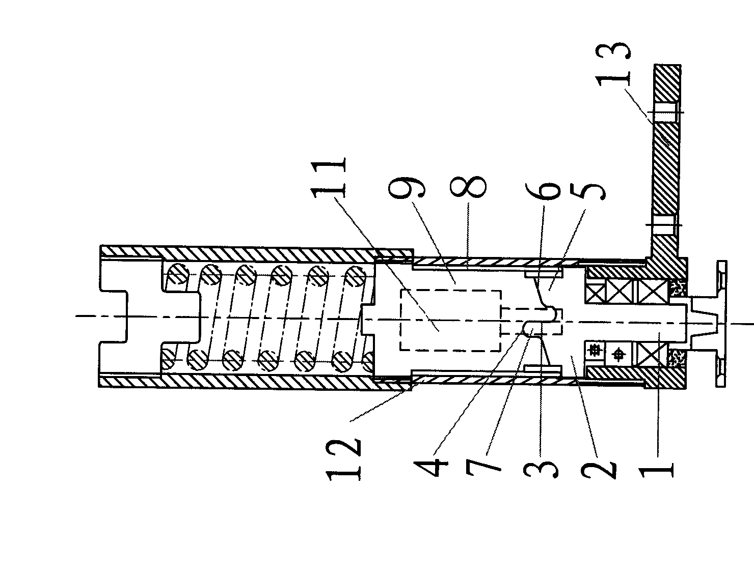
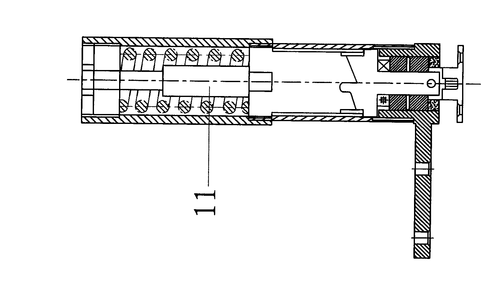
[0021] On the basis of Embodiments 1 and 2, the damper part 11 is fastened at the inner cavity between the upper hinge 2 and the lower hinge 9 (see figure 2 This example is a miniature damper assembly), or a damper part 11 is fastened at the end of the lower hinge 9 (see image 3 This example is the damper assembly) when the door is opened, the principle is the same as in embodiments 1 and 2. When the door is closed, the lower hinge 9 is slowly combined under the action of the damper when the door is closed, so as to avoid the impact sound when the two meshing gears are fully meshed, and achieve a quiet effect. Effect.


PUM


Abstract

The invention provides a vertical type ground hinge mechanism. An upper hinge and a lower hinge adopt a sliding friction pair comprising a pair of vertical annular meshing teeth, a meshing surface is a helical surface, the lateral end surfaces of the meshing teeth are vertical stopping surfaces, and the mutual meshing teeth are provided with positioning tooth sockets so as to form the vertical type ground hinge mechanism. The vertical type ground hinge mechanism converts the rotational motion of a hinge mechanism into straight line motion and has the advantages of simple structure, excellent firmness and duration, heavy load-bearing weight and accurate and steady positioning, and can be widely used in opened hinge mechanisms, such as doors, windows, and the like.

Description

technical field [0001] The invention improves the structure of the existing hinge device, especially the cam mechanism of the floor spring, and belongs to the technical field of door and window hardware. Background technique [0002] The present invention is based on "ground hinge" (utility model patent number: 200820126560.1), which has been widely used as a hinge mechanism for doors and windows. In the process of rotating and opening, the eccentric wheel on it is positioned by a pair of positioning wheels arranged on the left and right sides between the upper and lower plates, which not only makes the surface contour of the eccentric wheel very complicated, but also makes it difficult to manufacture and increase the cost. The wheels are easy to break, the service life is short, the bearing capacity is low, the positioning is unstable, and the application occasions are limited, especially for heavy doors, fire doors or one-way opening and closing occasions with relatively h...

Claims


Application Information

Patent Timeline
Patent Type & Authority Applications(China)
IPC IPC(8): E05F1/12E05F1/06
Inventor 秦源张丽霞秦中银
Owner 秦中银
Why Eureka
Try Eureka