Method and digital TV receiving terminal for mounting storage device

A digital TV receiving and storage device technology, applied in the direction of TV, electrical digital data processing, electrical components, etc., can solve the problems of reducing the success rate of storage devices, not being able to know the detection status of storage devices, and poor operability, so as to improve the success rate Effect

Inactive Publication Date: 2010-02-17
SHENZHEN COSHIP ELECTRONICS CO LTD
View PDF0 Cites 9 Cited by
  • Summary
  • Abstract
  • Description
  • Claims
  • Application Information

AI Technical Summary

Problems solved by technology

[0015] It can be seen from the method for mounting a USB storage device on a set-top box that the existing set-top box fails to mount a USB storage device. When the storage device is detected, the set-top box does not feed back the information that the USB storage device is being detected to the user during the detection process. , the user cannot know the detection status of the storage device, and the operability is poor, which reduces the user's satisfaction with the application of the storage device; furthermore, the storage capacity of the existing storage device is generally large, and the time required for detection is long, which makes the user During the longer detection period, because there is no prompt information, it is considered that the storage device has not been identified, so the storage device is pulled out, which reduces the success rate of the storage device mount; and, when the storage device is pulled out, Since the storage device is in the process of detection, the user can only use the operation of forcibly pulling out the storage device, which may cause errors in the operating system of the set-top box and illegal operation of the storage device, affecting the subsequent use of the storage device and reducing the subsequent mounting of the storage device. success rate

Method used


Image

  • Method and digital TV receiving terminal for mounting storage device
  • Method and digital TV receiving terminal for mounting storage device
  • Method and digital TV receiving terminal for mounting storage device

Examples


Embodiment Construction

[0049] In order to make the object, technical solution and advantages of the present invention clearer, the present invention will be further described in detail below in conjunction with the embodiments and accompanying drawings.

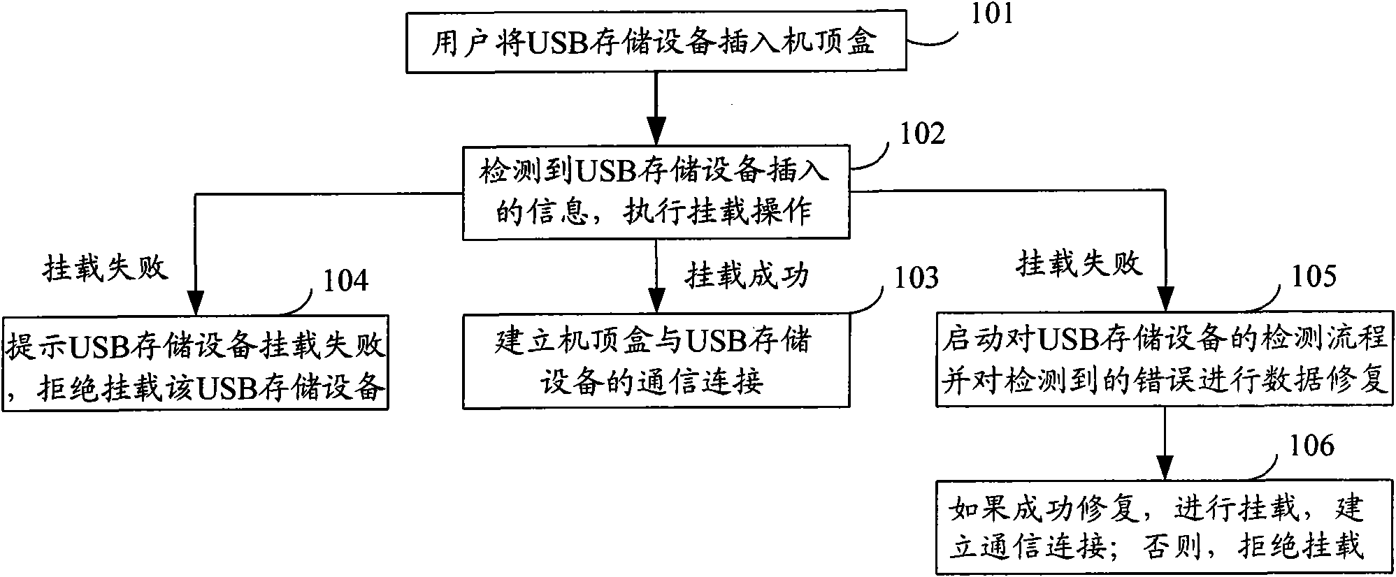
[0050] The invention sends detection-related information to the user when the operating system software of the set-top box detects the storage device, and the user can know the mounting state of the storage device in real time.

[0051] The following still takes the set-top box in the digital TV receiving terminal adopting the STMicroelectronics chip series platform technology solution as an example to describe the mounting of the USB storage device. It should be noted that this method can also be applied to storage devices such as mobile hard disks and MP3s.

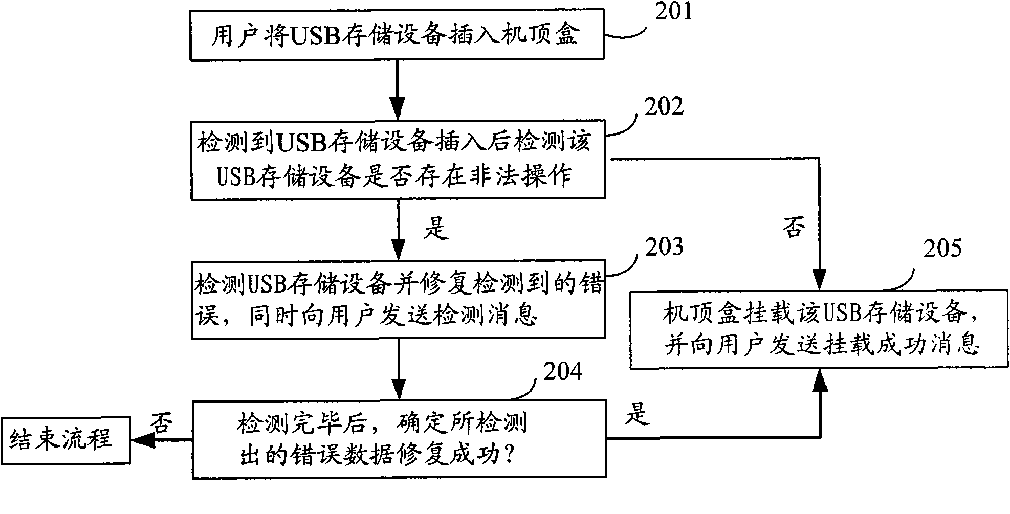
[0052] figure 2 For a schematic diagram of the overall flow of the method for mounting a USB storage device on a set-top box of the present invention, see figure 2 , the process includes...


PUM


Abstract

The invention discloses a method for mounting a storage device, comprising the following steps: detecting the insertion of the storage device and judging whether the inserted storage device carries out illegal operation or not, if so, entering the next step; detecting the storage device, restoring the detected error data and sending a detected message to a user; confirming that the error data aresuccessfully restored and mounting the storage device. The invention also discloses a digital TV receiving terminal for mounting the storage device. By applying the method and the digital TV receivingterminal for mounting the storage device, the user can know the mounting state of the storage device in real time, thereby avoiding the illegal operation caused by drawing the device out by the userwho considers that the storage device is not identified because no any prompting information appears in a long-term detecting process, and improving the success ratio of mounting the storage device.

Description

technical field [0001] The invention relates to equipment identification technology, in particular to a method for mounting a storage device and a digital TV receiving terminal for mounting the storage device. Background technique [0002] Storage devices such as USB storage devices, mobile hard disks, and MP3s have been widely used in various digital products such as PCs and handheld devices. When the user needs to use the storage device, insert the storage device into the digital product, the digital product detects that a storage device is inserted, and executes the mount operation. If the mount is successful, the communication connection between the storage device and the digital product is established; if If the mounting is unsuccessful, the user is prompted that the storage device has failed to mount, or the detection process of the storage device is started, and after the detection is completed, the storage device is mounted to the digital product, and the communicati...

Claims


Application Information

Patent Timeline
IPC IPC(8): G06F13/10H04N17/00
Inventor 黄玲忠
Owner SHENZHEN COSHIP ELECTRONICS CO LTD
Why Eureka
Try Eureka