Conveyor device

A conveying device and conveying belt technology, which is applied to conveyor objects, transportation and packaging, electrical components, etc., can solve the problems of reducing production efficiency and increasing equipment cost investment, and achieve the effect of improving production efficiency and reducing cost investment.

Inactive Publication Date: 2010-02-17
SHENZHEN FUTAIHONG PRECISION IND CO LTD
View PDF0 Cites 5 Cited by
  • Summary
  • Abstract
  • Description
  • Claims
  • Application Information

AI Technical Summary

Problems solved by technology

[0005] However, the method of installing infrared sensors at the end of the conveying device not only increases the cost of the equipment, but also reduces the production efficiency to a certain extent.

Method used


Image

  • Conveyor device

Examples


Embodiment Construction

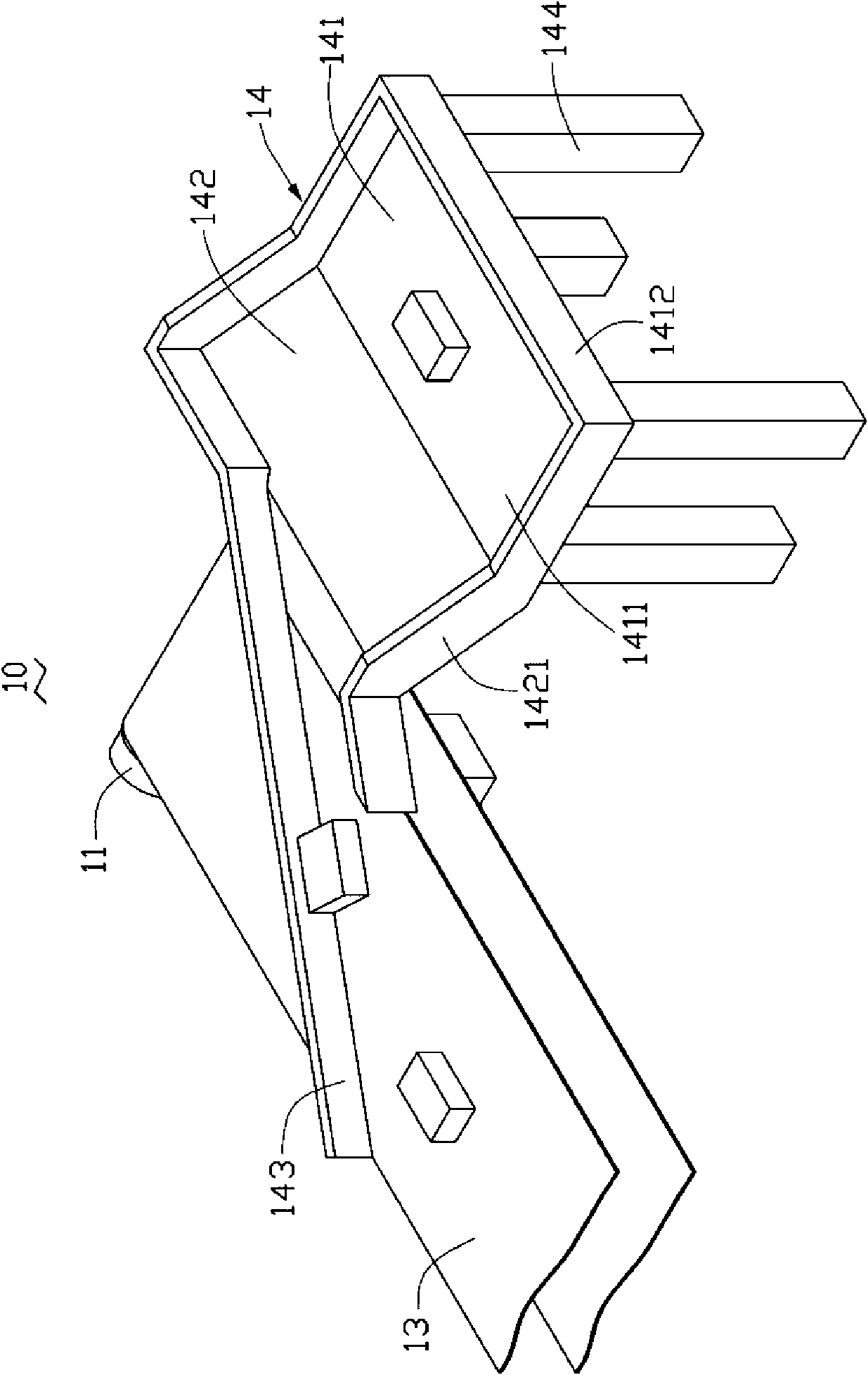
[0010] see figure 1 A preferred embodiment of the conveying device of the present invention is shown. The conveying device 10 includes a support 11 , roller shafts (not shown), a conveyor belt 13 and a wire take-up device 14 .

[0011] The support 11 can be formed by connecting several pillars to support the roller shaft 12 and the conveyor belt 13 .

[0012] The roller shaft is rotatably supported on the bracket 11 so that the conveyor belt 13 is sheathed and tensioned thereon.

[0013] The wire take-up device 14 includes a storage area 141 , a sliding plate 142 , a baffle plate 143 and four legs 144 .

[0014] The storage area 141 includes a bottom plate 1411 and a peripheral wall 1412 surrounding the bottom plate 1411 .

[0015] The sliding plate 142 is connected to the bottom plate 1411 at an obtuse angle, and two sides adjacent to the bottom plate 1411 are also provided with sidewalls 1421 . The side wall 1421 is integrally connected with the peripheral wall 1412 .

...


PUM


Abstract

The invention provides a conveyor device, comprising a conveyor belt and a wind-up device. The wind-up device comprises a storage area and a baffle, the baffle is arranged at the position corresponding to the storage area above the conveyor belt and used for leading conveying objects into the storage area.

Description

technical field [0001] The invention relates to a transmission device, in particular to a transmission device capable of automatically taking up wires. Background technique [0002] With the development of electronic technology, electronic devices have entered thousands of households, such as telephones, fax machines and computers. [0003] Nowadays, the assembly of electronic devices mostly adopts the method of conveying device operation, that is, the components of electronic devices are placed on a conveying device, and after passing through several stations, each station completes at least one process, and the electronic device is completed in sequence. assembly. [0004] This can lead to accumulation of product on the conveyor due to the varying levels of technical proficiency of the operators at each station. In order to solve this problem, the industry usually installs an infrared sensor at the end of the conveying device, that is, if a product flows from the upstrea...

Claims


Application Information

Patent Timeline
Patent Type & Authority Applications(China)
IPC IPC(8): H05K13/02
CPCB65G47/519B65G47/763
Inventor 李嘉恩杨勇
Owner SHENZHEN FUTAIHONG PRECISION IND CO LTD
Why Eureka
Try Eureka