Support mould upright post for cast wall bodies

A technology for supporting formwork columns and walls, which is applied to the connection parts of formwork/formwork/work frame, the on-site preparation of building components, and construction, etc., can solve the problems of high cost, troublesome operation, time-consuming and laborious, etc.

Inactive Publication Date: 2010-02-24
杨小平
View PDF0 Cites 0 Cited by
  • Summary
  • Abstract
  • Description
  • Claims
  • Application Information

AI Technical Summary

Problems solved by technology

[0003] The purpose of the present invention is to overcome the technical problems caused by unreasonable design such as complex structure, time-consuming and labor-intensive, high cost and troublesome operation of the existing equipment for fixing formwork when pouring walls, and to provide people with a simple structure and convenient operation. , saving labor and time, low cost and high efficiency formwork columns for pouring walls

Method used


Image

  • Support mould upright post for cast wall bodies
  • Support mould upright post for cast wall bodies
  • Support mould upright post for cast wall bodies

Examples


Embodiment 1

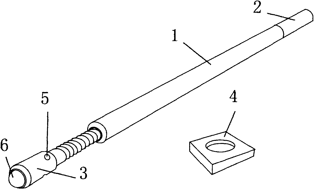
[0022] Formwork columns are used for pouring walls in this example, such as Figure 1 As shown, it is a formwork column with a jack device, which is composed of an upper strut 1 and a bottom jack. The bottom end of the strut 1 is connected with the upper end of the jack. 2 and support rod 1 socket or screw fit. The jack is a screw jack, which consists of a telescopic adjustment rod 3, a base 4 with a circular groove and a rotating device 5, wherein the bottom end of the strut 1 and the upper end of the telescopic adjustment rod 3 are threaded, and the bottom end of the telescopic adjustment rod 3 A movable ball 6 matched with the circular groove on the base 4 is provided, and the rotating device 5 is a hole arranged on the telescopic adjusting rod 3, and the telescopic adjusting rod 3 is rotated by an iron rod inserted into the hole.

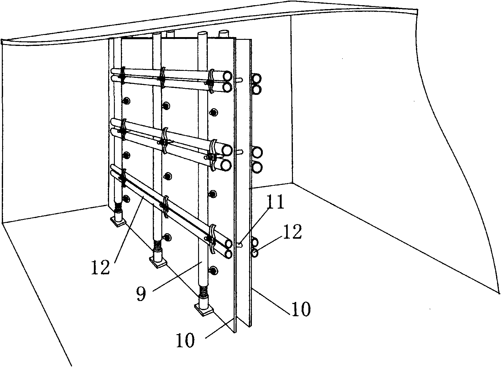
[0023] When used, such as Figure three As shown, the base 4 is placed at a certain distance on the positioning line of the wall to be poured...

Embodiment 2

[0025] Formwork columns are used for pouring walls in this example, such as Figure 1 Shown, except screw jack, all the other are the same as embodiment one.

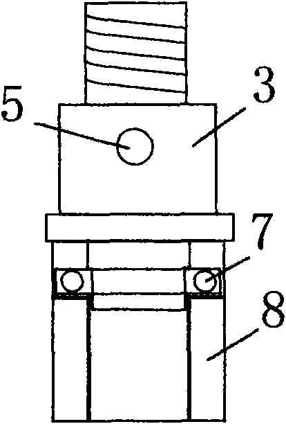
[0026] The screw jack used in this example is composed of a telescopic adjusting rod 3, a bearing 7, a bearing seat 8 and a rotating device 5, wherein the bottom end of the strut 1 and the upper end of the telescopic adjusting rod 3 are threaded, and the bottom of the telescopic adjusting rod 3 The end is connected with the bearing seat 8 through the bearing 7, and the rotating device 5 is a hole arranged on the telescopic adjustment rod 3, and the telescopic adjustment rod 3 is rotated by the iron rod inserted in the hole.

Embodiment 3

[0028] The pouring wall of this example uses formwork uprights, and except jack, all the other are with embodiment one. The jack used in this example is an existing hydraulic jack.


PUM


Abstract

The invention belongs to the field of building equipment, in particular to a support mould upright post for cast wall bodies. The support mould upright post is characterized in that the support mouldupright post is provided with a lifting jack and consists of a support rod (1) on the upper part and the lifting jack on the bottom part, wherein the bottom end of the support rod(1) is in matched connection with the upper end of the lifting jack. The support rod (1) is also provided with a spiral fastener or a through hole matched with a mould plate through hole; the top end of the support rod (1) is provided with an insertion rod (2) which is matched with the support rod (1) by insertion or threads; and the lifting jack may be a spiral type lifting jack, a hydraulic type lifting jack, a lever type lifting jack, an inclined plane type lifting jack or an electric type lifting jack. The invention provides the support mould upright post, which has the advantages of simple structure, easy operation, labor and time conservation, low cost and high efficiency.

Description

Technical field: [0001] The invention belongs to the field of construction equipment, and in particular relates to a formwork column for pouring walls. Background technique: [0002] In the prior art, in the in-situ forming construction of building walls and other similar building constructions, it is often necessary to use formwork to build a wall pouring cavity formed by formwork on both sides, and then pour and solidify to form an in-situ forming wall. However, due to the large size of the wall to be formed and the lack of fixed supports, the positioning and fixing of the formwork is a very troublesome problem. Using existing methods such as binding to fix it is time-consuming and laborious. It is not only laborious but also costly and efficient. Low, so the application and promotion are more difficult. Invention content: [0003] The purpose of the present invention is to overcome the technical problems caused by unreasonable design such as complex structure, time-con...

Claims


Application Information

Patent Timeline
IPC IPC(8): E04G17/14
Inventor 杨小平
Owner 杨小平
Why Eureka
Try Eureka