Support mould method for cast-in-situ wall bodies
A form-supporting method and cast-in-place wall technology are applied in the on-site preparation of building components, formwork/formwork/work frame, formwork/formwork/work frame connectors, etc. The problems of high labor intensity and long construction time can achieve the effect of convenient construction, labor saving and low cost
- Summary
- Abstract
- Description
- Claims
- Application Information
AI Technical Summary
Problems solved by technology
Method used
Image

Examples
Embodiment 1
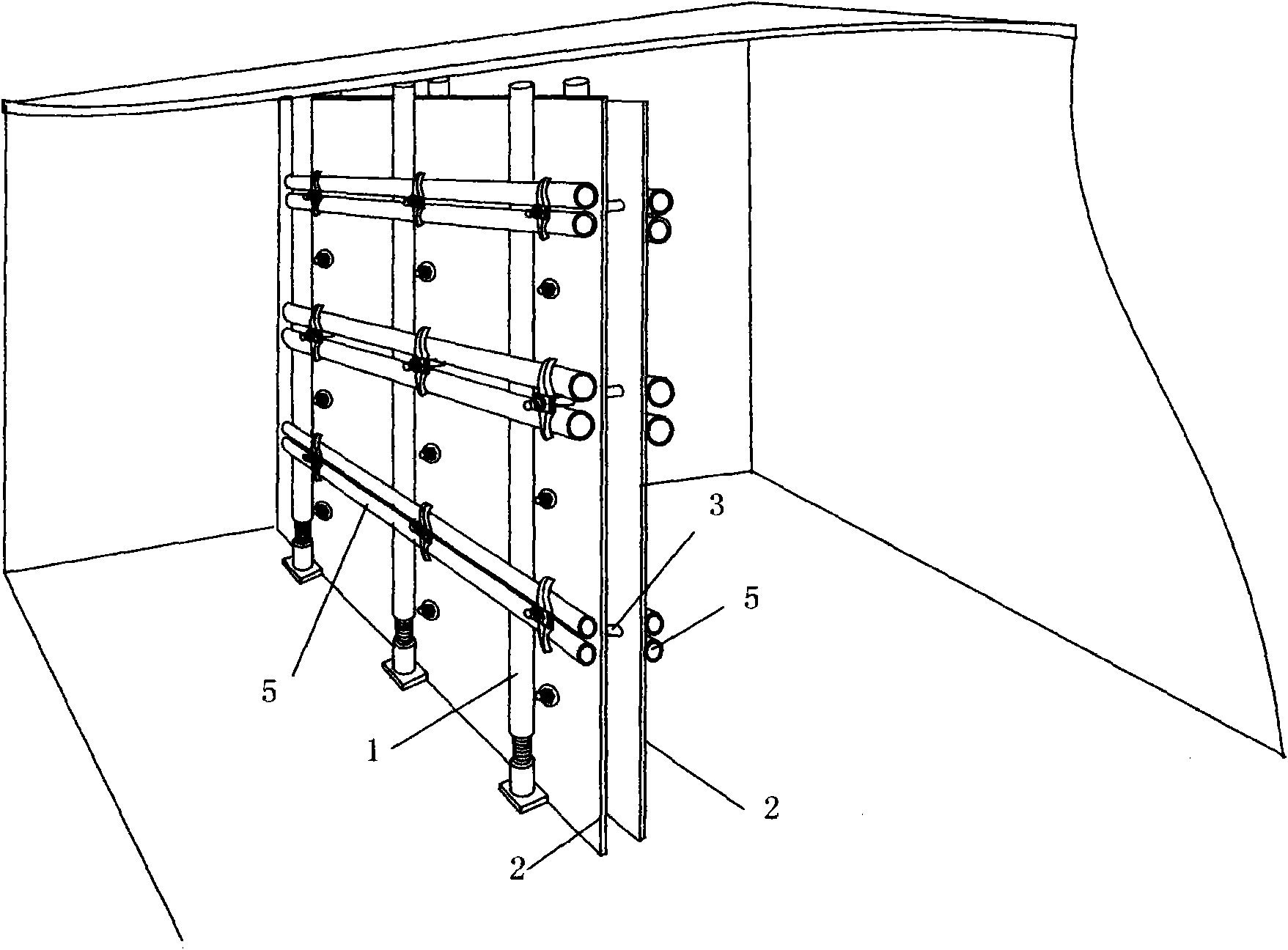
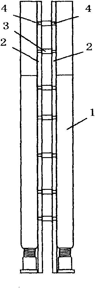
[0030] The formwork support method of the cast-in-place wall in this example is as follows: Figure II As shown, first, space the formwork columns 1 with screw jacks at a certain distance along the positioning line of the wall, and fix them between the building ceiling or the beam and the floor, and fix one formwork 2 on the formwork columns with screw jacks 1 On one side, the wall thickness measuring piece 3 is fixed on the through hole 4 of the formwork 2, the other side formwork 2 is close to the wall thickness measuring piece 3, and the other side formwork 2 is fixed by the formwork column 1 with a screw jack , and deliver it.
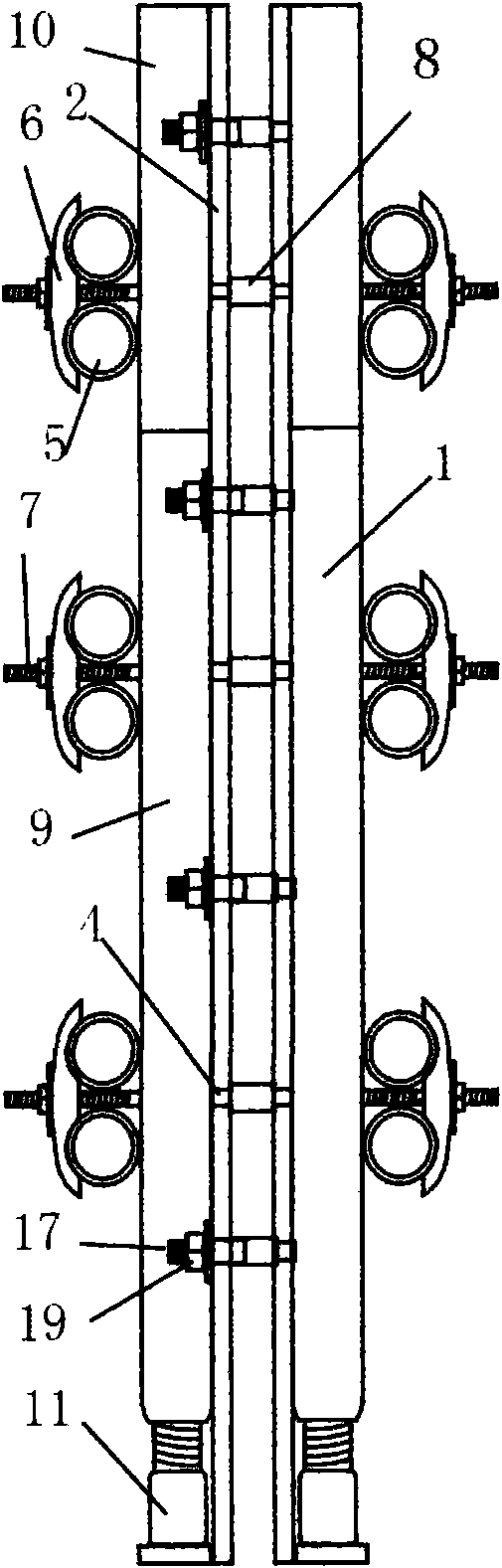
[0031] Among them, the formwork column 1 with the screw jack used in this example is as Figure four As shown, it is composed of the upper strut 9 and the screw jack at the bottom, the bottom end of the strut 9 is connected with the upper end of the screw jack, and the top of the strut 9 is provided with an insertion rod 10 to adjust the length of...
Embodiment 2
[0035] The formwork support method of the cast-in-place wall in this example is as follows: Figure 1 and Figure threeAs shown, first, space the formwork columns 1 with screw jacks at a certain distance along the positioning line of the wall, and fix them between the building ceiling or the beam and the floor, and fix one formwork 2 on the formwork columns with screw jacks 1 On one side, the wall thickness measuring piece 3 is fixed on the through hole 4 of the formwork 2, and the wire pipe and wire box are pre-embedded according to the construction drawings, and then the other side of the formwork 2 is close to the wall thickness measuring piece 3, with a belt After the formwork column 1 of the screw jack and the ordinary formwork column are fixed on the other side of the formwork 2, the horizontal back flute 5 is fixed on the formwork column 1 with the screw jack and the ordinary formwork column with fasteners, and then delivered for use .
[0036] The used formwork colum...
Embodiment 3
[0040] The formwork supporting method of the cast-in-place wall of this example is except used screw type jack and wall body thickness measuring part 3, all the other are the same as embodiment two.
[0041] The screw jack used in this example is as Figure five As shown, it is composed of a telescopic adjusting rod 11, a bearing 15, a bearing seat 16 and a rotating device 13, wherein the bottom end of the strut 9 is threadedly matched with the upper end of the telescopic adjusting rod 11, and the bottom end of the telescopic adjusting rod 11 passes through the bearing 15 Connected with the bearing seat 16, the diameter of the bearing seat 16 is the same as that of the strut 9, the rotating device 13 is a hole arranged on the telescopic adjustment rod 11, and the telescopic adjustment rod 11 is rotated by the iron rod inserted into the hole to adjust the strut 9 in height.
[0042] The wall thickness measuring part 3 used in this example is as Figure ten As shown, it is a c...
PUM
 Abstract
Description
Claims
Application Information
 - Generate Ideas
- Intellectual Property
- Life Sciences
- Materials
- Tech Scout
- Unparalleled Data Quality
- Higher Quality Content
- 60% Fewer Hallucinations
Browse by: Latest US Patents, China's latest patents, Technical Efficacy Thesaurus, Application Domain, Technology Topic, Popular Technical Reports.
© 2025 PatSnap. All rights reserved.Legal|Privacy policy|Modern Slavery Act Transparency Statement|Sitemap|About US| Contact US: help@patsnap.com