Method for simulating electric drive control system under brake working condition of electric-wheel truck

A technology for electric wheel vehicles and dynamic braking, applied in general control systems, control/regulation systems, brakes, etc., can solve the problems of increased system debugging, difficulty in controller design, difficulty, etc., to save experimental costs and shorten development cycles. Effect

Active Publication Date: 2010-02-24
ANSTEEL GRP MINING CO LTD
View PDF0 Cites 8 Cited by
  • Summary
  • Abstract
  • Description
  • Claims
  • Application Information

AI Technical Summary

Problems solved by technology

[0004] According to the conventional design ideas, not only the derivation and calculation of each link is very complicated, but also the controller design of the overall structure of the system is also very difficult, which also increases the difficulty of system debugging

Method used


Image

  • Method for simulating electric drive control system under brake working condition of electric-wheel truck
  • Method for simulating electric drive control system under brake working condition of electric-wheel truck
  • Method for simulating electric drive control system under brake working condition of electric-wheel truck

Examples


Embodiment Construction

[0035] The specific implementation manner of the present invention will be further described below in conjunction with the accompanying drawings.

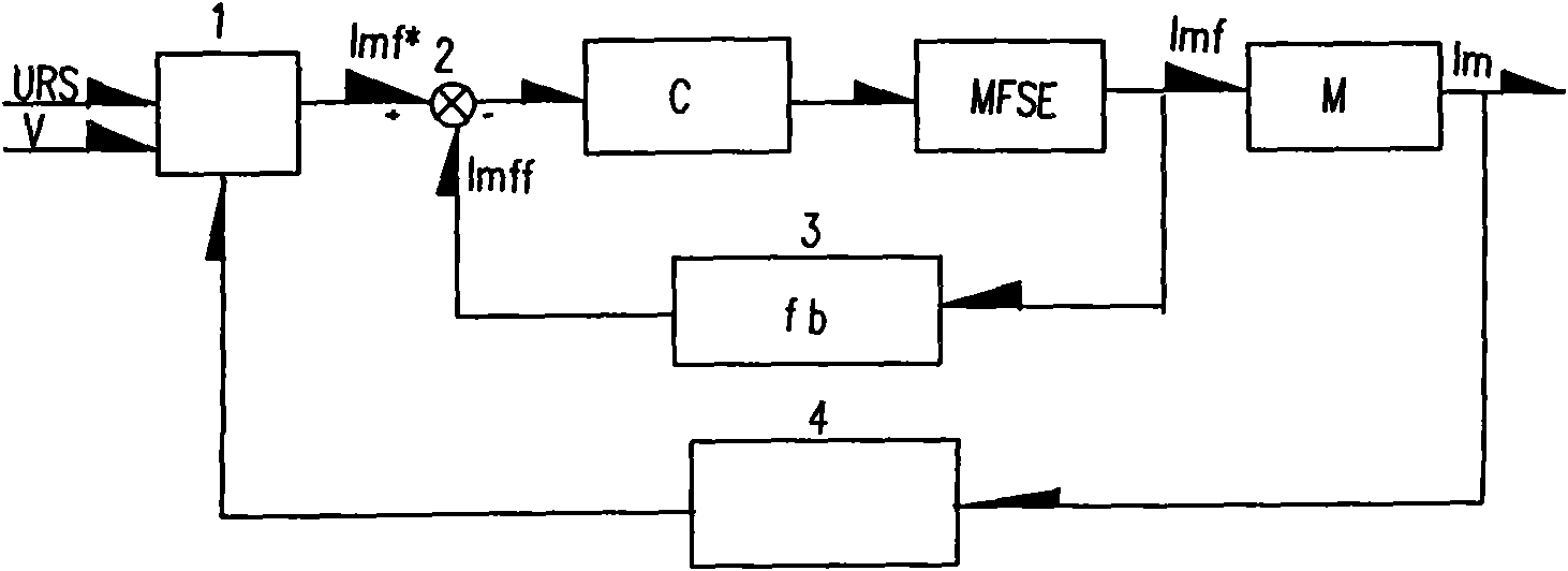
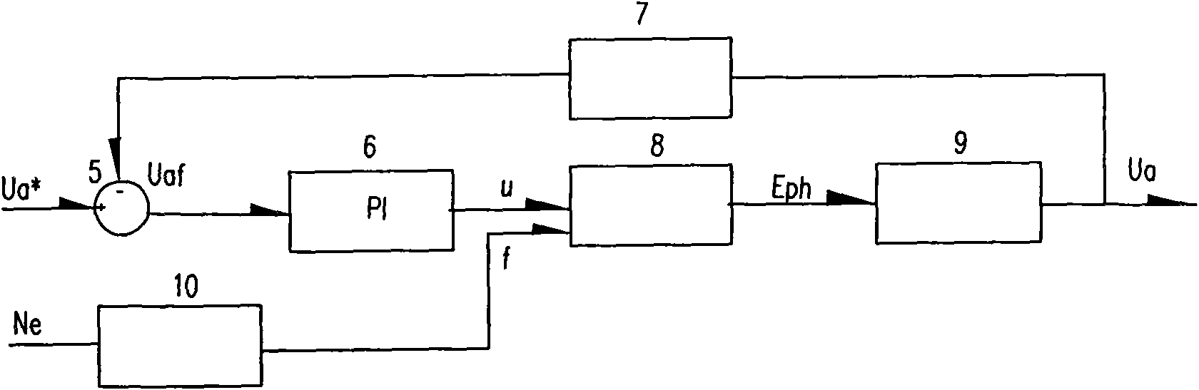
[0036] The simulation method of the electric transmission control system under the dynamic braking condition of an electric wheel vehicle according to the present invention is characterized in that under the dynamic braking condition, the control system is composed of a wheel motor control part and a main generator control part:

[0037] 1) wheel motor control part:

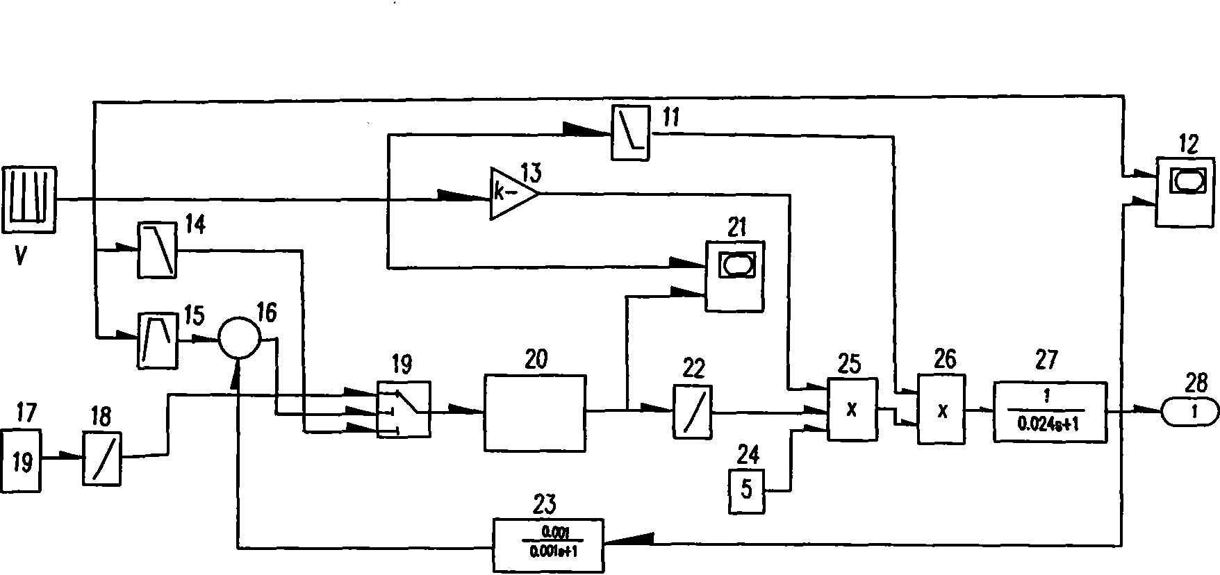
[0038] (1) Calculate the characteristic curves of excitation current and armature current according to the data of relevant technical materials,

[0039] (2) Analyze the working logic under braking conditions, and get U RS -Imf*, V-Imf*, V-Ia*, Imf*-Imf, V-1 / R characteristic curves of each link, where U RS is the brake pedal signal, Imf* is the excitation current of the wheel motor, V is the vehicle speed, Ia* is the armature current of the wheel motor, Imf is the e...


PUM


Abstract

The invention relates to application of computer simulation in an electric drive control system under a brake working condition of an electric-wheel truck, in particular to a method for simulating theelectric drive control system under the brake working condition of the electric-wheel truck. Under the power brake working condition, the control system consists of a wheel motor control part and a main generator control part, wherein the wheel motor control part calculates to obtain characteristic curves of excitation current and armature current according to related data, analyzes the working logic under the brake working condition, obtains characteristic curves of various links such as URS-Imf*, V-Imf*, V-Ia*, Imf*-Imf, and B-1 / R, and combines the power brake characteristics of the wheel motor to establish a simulation map of a wheel motor part under the power brake working condition in a Simullink environment; and the main generator control part establishes a simulation map of a maingenerator part under the power brake working condition in the Simulink environment by combining the main generator structure according to a main generator control schematic diagram. The method verifies the correctness of a scheme by comparing a simulation result and a demand characteristic curve of the system.

Description

technical field [0001] The invention relates to the application of computer simulation in the electric transmission control system under the dynamic braking condition of the electric wheel vehicle, in particular to a simulation method of the electric transmission control system under the dynamic braking condition of the electric wheel vehicle. Background technique [0002] Electric wheel vehicles are ideal and efficient transportation equipment in large-scale open-pit mines at home and abroad, and play an extremely important role. Its electric transmission adopts the STATEXIII type control system of GE Company of the United States. This system can control the car in real time, and through the online dialogue of the notebook computer, the relevant running data of the car can be obtained. [0003] However, it does not reveal the control structure of the system under dynamic braking conditions, so that users and researchers of the system cannot know the logical relationship of ...

Claims


Application Information

Patent Timeline
Patent Type & Authority Applications(China)
IPC IPC(8): G05B17/02B60T8/17
Inventor 苍晴
Owner ANSTEEL GRP MINING CO LTD
Why Eureka
Try Eureka