Optical performance recovery device, recovery method and optical system used for the device

A technology of optical system and optical equipment, applied in the field of invention, can solve problems such as difficult long-term monitoring

Inactive Publication Date: 2013-06-19
MITSUBISHI HEAVY IND LTD
View PDF2 Cites 0 Cited by
  • Summary
  • Abstract
  • Description
  • Claims
  • Application Information

AI Technical Summary

Problems solved by technology

Therefore, it is difficult to use this lamp for occasions that require long-term monitoring such as environmental measurements

Method used


Image

  • Optical performance recovery device, recovery method and optical system used for the device
  • Optical performance recovery device, recovery method and optical system used for the device
  • Optical performance recovery device, recovery method and optical system used for the device

Examples


Embodiment 1

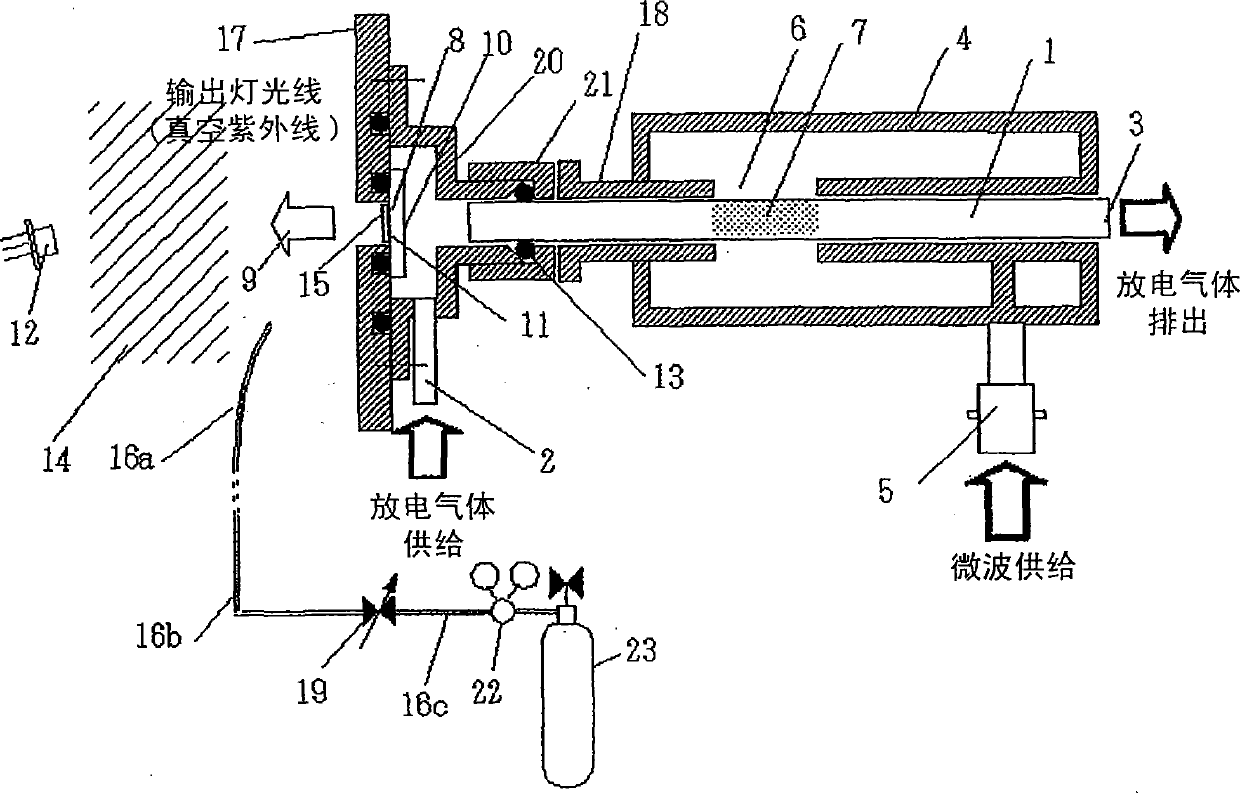
[0135] figure 1 It is a diagram showing the structure of the microwave excited hydrogen ultraviolet lamp according to the first example of the first preferred embodiment of the present invention.

[0136] The holder (flange) 17 connected to the light transmission window 8 is of a disc shape, and its center is aligned with the hole of the discharge tube 1, and it includes an opening with a larger diameter than the inner diameter of the discharge tube. The window flange 17 includes an O-ring groove to seal the entire opening of the light transmission window 8, a hollow cover-shaped assembly frame 20, a bolt hole for attaching it, and is connected to the discharge tube 1 for use with a window flange 17 O-ring groove to maintain vacuum.

[0137] The internal structure of the assembling frame 20 adopts two levels of concentric circles and limits the space for accommodating the light transmission window 8 and the space surrounded by the discharge tube 1. At the end surrounding the disc...

Embodiment 2

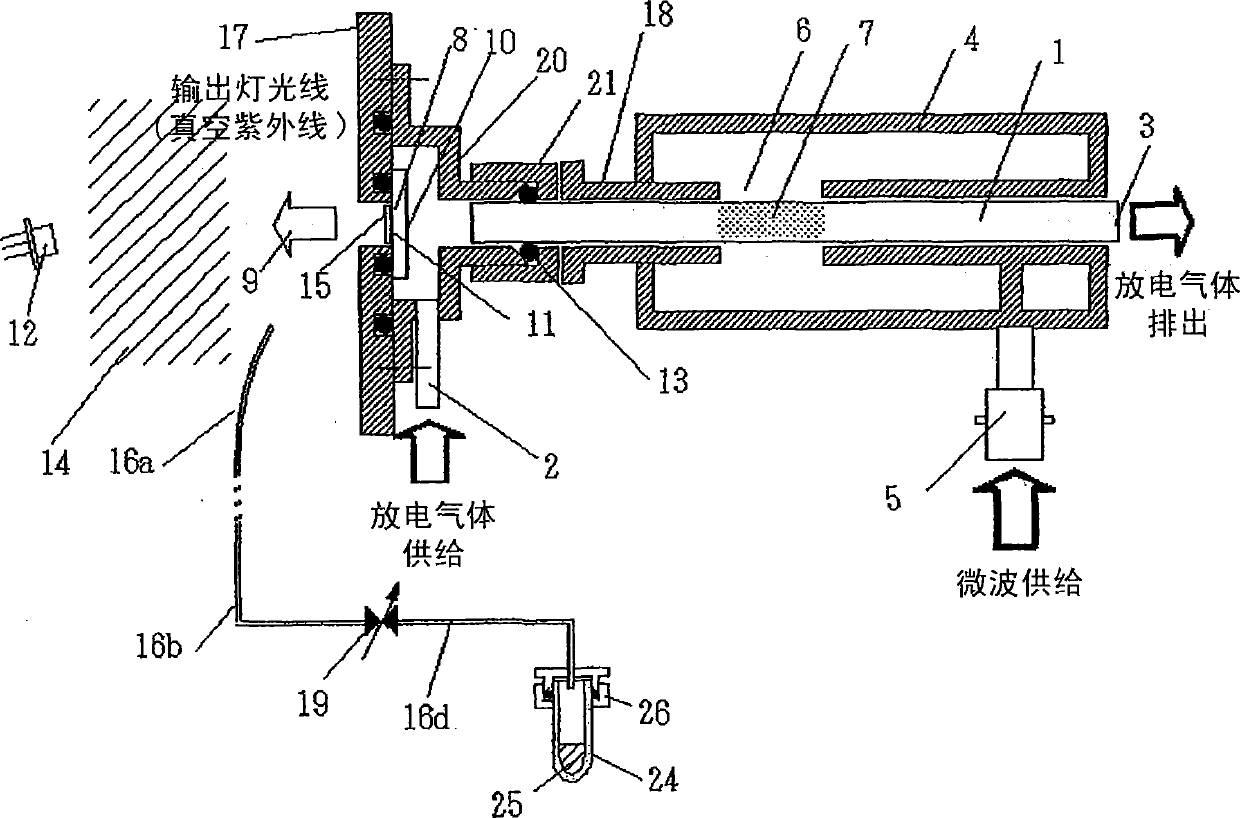
[0161] figure 2 It is a diagram showing a microwave-excited hydrogen ultraviolet lamp for explaining the second example of the first preferred embodiment of the present invention. Other detailed descriptions of the same structure and operating elements as those described in Embodiment 1 are omitted here. The specifications of the light transmission window 8 are the same as those described in the first embodiment. In addition, the photodiode 12 is positioned as a device for monitoring the light output of the lamp to receive the light output of the light emitted by the lamp 9.

[0162] The steam is supplied to the vacuum zone 14 by the following method and adjusted to a prescribed gas partial pressure. A glass tube 24 (diameter of Φ6 mm) filled with 1 mL of water 25 (purified water for distillation, ion exchange treatment, and filtration) is connected to a tube 16d through a flange 17. The structure of the flange 17 of the combined O-ring seals the glass tube to isolate it from ...

Embodiment 3

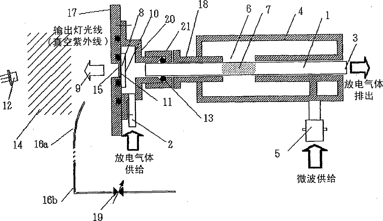
[0173] image 3 It is a diagram showing a microwave-excited hydrogen ultraviolet lamp for explaining the third example of the first preferred embodiment of the present invention. Other detailed descriptions of the same structure and operating elements as those described in Embodiment 1 are omitted here. The specifications of the light transmission window 8 are the same as those described in the first embodiment. In addition, the photodiode 12 as a device for monitoring the output of the lamp is positioned to receive the light output of the light 9 emitted by the lamp.

[0174] The atmospheric components are supplied to the vacuum zone 14 and adjusted to the prescribed gas partial pressure by the following prescribed method.

[0175] After passing through the adjustable hole of the variable leakage valve 19, the atmospheric components are supplied to the vacuum zone 14 through a tube open to the atmosphere allowing the atmospheric components to flow through the tube 16b, and enter ...


PUM


Abstract

The invention aims to prevent or suppress attenuation of an optical system which determines service life of an optical device, wherein the optical device realizes effects of light transmission, diffraction, reflection, spectrum generation and interference and combination thereof. Through using the said modes, frequency and cost of maintenance operation such as window replacement, can be reduced. The invention is characterized in realization by producing a near-vacuum area with presence of active energy, so as to excite oxidation reaction of carbon, wherein the near-vacuum area faces to a light surface of the optical system; producing anion or groups in the near-vacuum area, such as unstable groups containing oxygen atom, e.g. OH group, OH<-> ion, ozone, O2<-> ion, O<-> group; reacting with anion or groups through deposited carbon, so as to eliminate or reduce accumulated carbon accumulated on a lighting surface.

Description

[0001] This application is a divisional application of the patent application with the filing date of "May 31, 2004", the application number of 200410046441.1, and the invention title of "Optical Performance Recovery Equipment, Recovery Method, and Optical System Used in the Equipment". Technical field [0002] The present invention relates to an apparatus and method for improving the reliability and life of the optical system by preventing, suppressing or improving the attenuation of the optical performance of the optical system existing in the output light or along the light path of the output light , Wherein the optical system is set in a near-vacuum area where organic components can be decomposed, and the attenuation is deposited or accumulated on the light irradiating surface, light reflecting surface, and light emitting surface of the optical system (collectively referred to as "light surface") The carbon on the surface is generated while the surface faces the vacuum zone. ...

Claims


Application Information

Patent Timeline
Patent Type & Authority Patents(China)
IPC IPC(8): H01J61/00B08B7/00
Inventor 坂井智嗣鹤我薰典山越英男栗林志头真团野实二见博山崎纪子
Owner MITSUBISHI HEAVY IND LTD
Why Eureka
Try Eureka