Check patentability & draft patents in minutes with Patsnap Eureka AI!

Improved umbrella

A technology for umbrella covers and umbrella poles, which can be applied to umbrellas, travel goods, clothing, etc., and can solve problems such as increased pressure differential resistance

Inactive Publication Date: 2010-02-24
史蒂文·J·霍林格
View PDF4 Cites 3 Cited by
  • Summary
  • Abstract
  • Description
  • Claims
  • Application Information

AI Technical Summary

Problems solved by technology

When the wind contacts a conventional canopy as shown at 575, the windward portion 577 presses inwards, flattening its positive curvature surface and ultimately increasing the pressure differential resistance

Method used


Image

  • Improved umbrella
  • Improved umbrella
  • Improved umbrella

Examples


Embodiment Construction

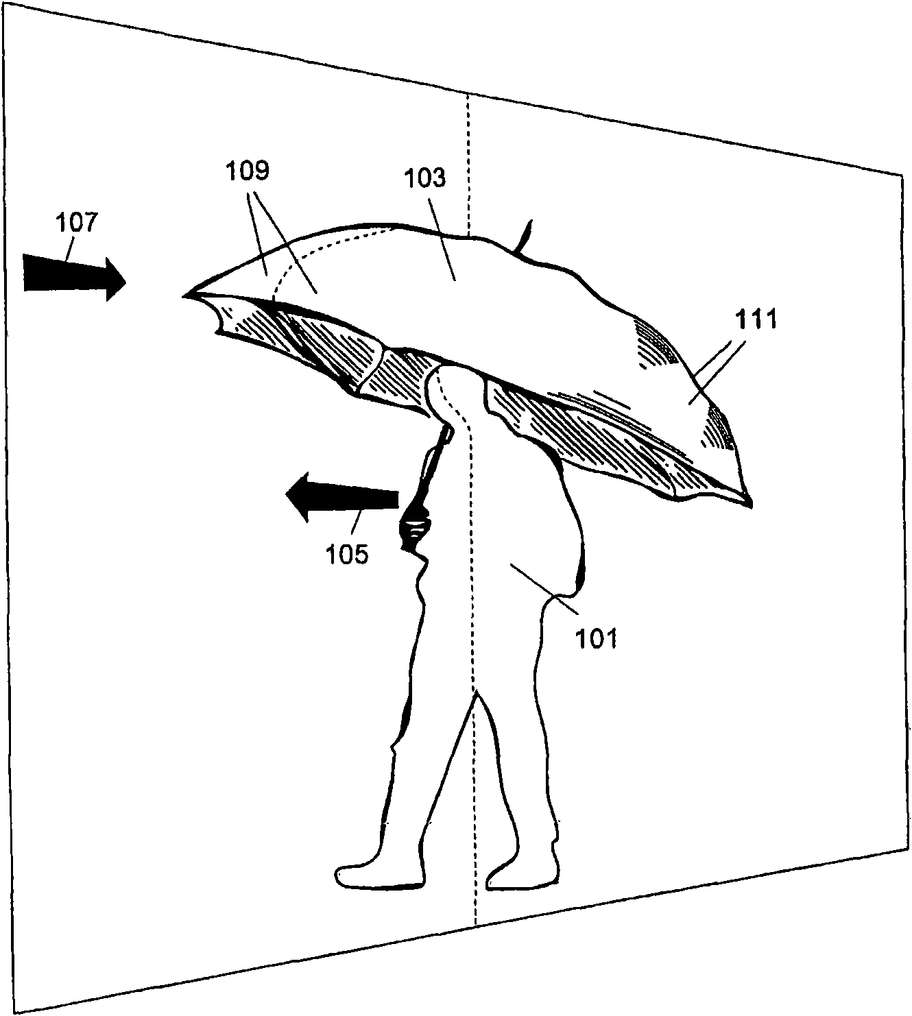
[0089] As an object that interacts with the wind, the traditional umbrella can be defined and improved in terms of its aerodynamic properties. An understanding of the dynamics of low-speed airflow around a moving body helps to produce optimal designs for bicycle helmets, Frisbees and model airplanes.

[0090] In the field of low-speed aerodynamics, spherical and cylindrical shapes are called bluff shapes, which are determined by the pressure differential drag between a high-pressure area on the windward side and a low-pressure area on the leeward side. Objects determined by frictional resistance rather than differential pressure resistance are considered to be streamlined. In order to hold the canopy in place or to move forward while walking, the umbrella user must balance air resistance by applying a reaction force to the handle. Depending on the position of the handle relative to the center of pressure, air resistance can be leveraged through the umbrella shaft around the h...


PUM


Abstract

Umbrellas with improvements that make the umbrella easier to control. The improvements include an edge of the umbrella canopy that presents a convex surface to the flow of air across the canopy and that also may direct the flow of air away from the underside of the canopy and away from the user of the umbrella, gutters for directing the flow of water on the canopy, spoilers for modifying the flowof air across the canopy, windsocks that release air pressure under the canopy by inflating, and canopies with streamlined shapes, including shapes that may be modified by the user or modify themselves in response to the flow of air.

Description

[0001] Cross References to Related Applications [0002] This patent application claims priority to US Provisional Patent Application 60 / 642,542, filed January 10, 2005, entitled "Improved Umbrella Design" by Steve Hollinger. The entire content of this provisional patent application is incorporated by reference into this patent application. [0003] Statement Concerning Initiating Research or Development on a Commonwealth-wide basis [0004] Not applicable [0005] Sequence Listing Reference [0006] Not applicable technical field [0007] The present invention relates generally to umbrellas, and more particularly to umbrellas having a canopy and a support structure that stabilizes the canopy against wind. Background technique [0008] A conventional umbrella consists of a cloth canopy generally symmetrical to the longitudinal plane; an umbrella shaft; a plurality of ribs extending radially from a central point on the canopy and extending to the perimeter of the canopy; ...

Claims


Application Information

Patent Timeline
Patent Type & Authority Applications(China)
IPC IPC(8): A45B11/00A45B25/22
CPCA45B25/02A45B25/22
Inventor 史蒂文·J·霍林格
Owner 史蒂文·J·霍林格
Features
  • R&D
  • Intellectual Property
  • Life Sciences
  • Materials
  • Tech Scout
  • Unparalleled Data Quality
  • Higher Quality Content
  • 60% Fewer Hallucinations
Learn More