Low noise voltage reference circuit

A reference circuit and voltage reference technology, applied in the direction of adjusting electrical variables, instruments, control/regulation systems, etc., can solve problems that are difficult to achieve while minimizing circuit, reference voltage and voltage noise

Active Publication Date: 2010-02-24
ANALOG DEVICES INC
View PDF0 Cites 4 Cited by
  • Summary
  • Abstract
  • Description
  • Claims
  • Application Information

AI Technical Summary

Problems solved by technology

[0003] Although this circuit is capable of providing a temperature insensitive reference voltage, it has the disadvantage of somewhat having the effect of voltage noise on the generated refer...

Method used


Image

  • Low noise voltage reference circuit
  • Low noise voltage reference circuit
  • Low noise voltage reference circuit

Examples


Embodiment Construction

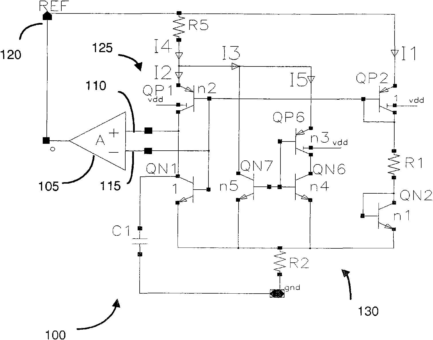
[0012] Such as figure 1 As shown, a bandgap voltage reference circuit 100 according to the concepts of the present invention includes a first amplifier 105 having a first input 110 and a second input 115 and providing a voltage reference at its output 120 . Coupled to the aforementioned first and second input terminals are a first pair of transistors 125 and a second pair of transistors 130 , respectively.

[0013] The first pair of transistors 125 comprises two bipolar transistors of pnp type: a first bipolar transistor QP1 and a second bipolar transistor QP2 of the circuit. The bases of each of the first and second transistors are coupled together, the first transistor is also coupled via its collector node to the amplifier input and via resistor R5 to the amplifier output 120 . The second transistor is provided in a diode configuration with its base and emitter commonly coupled.

[0014] A second pair of transistors 130 coupled to the second input terminal 115 includes tw...


PUM


Abstract

A low noise voltage reference circuit is described. The reference circuit utilizes a bandgap reference component and may include at least one of a current shunt or filter to reduce high and low noise contributions to the output. Further modifications may include a curvature correction component.

Description

technical field [0001] The invention relates to a voltage reference circuit based on a band gap, in particular to a voltage reference with very low noise. Background technique [0002] Voltage references are widely used in electronic circuits, especially in analog circuits where an electrical signal must be compared to a standard signal that remains stable over changing environmental conditions. The most hostile environmental factor for circuits on a chip is temperature. A reference voltage based on the bandgap principle consists of the sum of two voltages that vary inversely with temperature. The first voltage corresponds to a forward-biased PN junction having a voltage drop of about 2.2 mV / ° C. inversely to absolute temperature (CTAT, complementary to absolute temperature). A voltage proportional to absolute temperature (PTAT) is generated by amplifying the base-emitter voltage difference of two bipolar transistors operating at different collector current densities. A f...

Claims


Application Information

Patent Timeline
IPC IPC(8): G05F3/30
CPCG05F3/30
Inventor 斯特凡·玛林卡
Owner ANALOG DEVICES INC
Why Eureka
Try Eureka