Pulsation generating mechanism, connecting flow channel tube, and fluid ejecting apparatus

A technology of fluid jetting and connecting flow paths, applied in the fields of fluid jet scalpel, medical science, surgery, etc., it can solve the problems of insufficient internal pressure, rise, and inability to perform pulsating discharge, and achieve the effect of improving convenience.

Inactive Publication Date: 2010-03-03
SEIKO EPSON CORP
View PDF1 Cites 13 Cited by
  • Summary
  • Abstract
  • Description
  • Claims
  • Application Information

AI Technical Summary

Problems solved by technology

If air bubbles remain in the fluid chamber, there is a high possibility that when the volume is reduced, the internal pressure does not rise enough to perform pulsation discharge

Method used


Image

  • Pulsation generating mechanism, connecting flow channel tube, and fluid ejecting apparatus
  • Pulsation generating mechanism, connecting flow channel tube, and fluid ejecting apparatus
  • Pulsation generating mechanism, connecting flow channel tube, and fluid ejecting apparatus

Examples


Embodiment approach 1

[0063] Next, the configuration of the fluid ejection device 10 according to Embodiment 1 will be described.

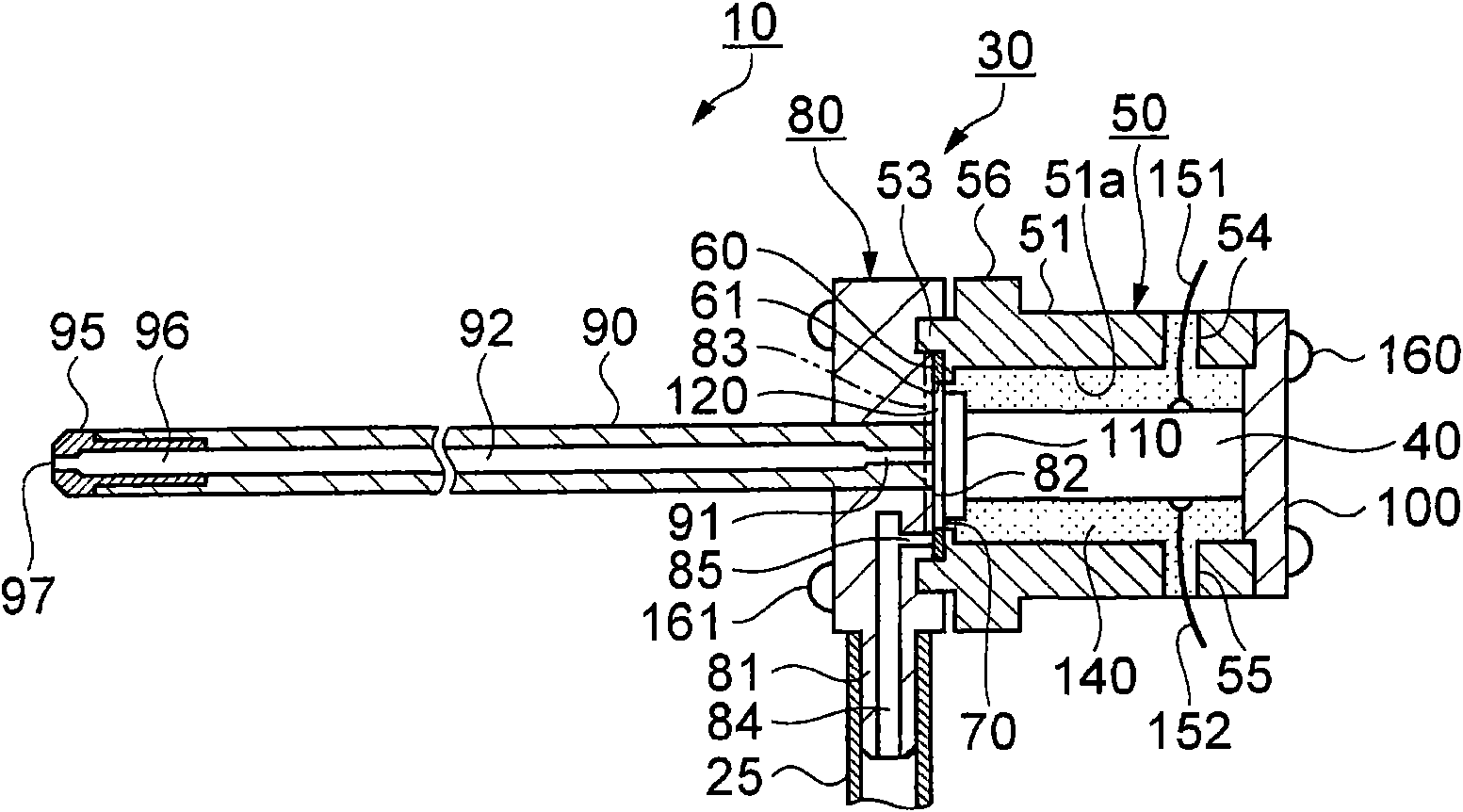
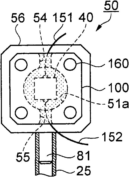
[0064] figure 2 It is a cross-sectional view showing the main structure of the pulsation generating mechanism according to Embodiment 1 cut along the flow path direction of the liquid, image 3 It is a side view shown from the right side of the pulsation generating mechanism, Figure 4 It is a side view shown from the left side of the pulsation generating mechanism.

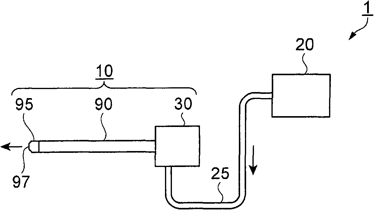
[0065] First, refer to Figure 2 ~ Figure 4 A schematic configuration of the fluid ejection device 10 will now be described. The fluid ejection device 10 is composed of: a pulsation generating mechanism 30 including a pulsation generating unit that generates pulsation of liquid; and a connection channel pipe 90 having an outlet connection channel 92 and a nozzle 95 for discharging liquid.

[0066] The pulsation generating mechanism 30 has a fluid chamber 120, and the fluid chamber 120 is configured s...

Embodiment approach 2

[0128] Next, Embodiment 2 will be described with reference to the drawings. Embodiment 2 has a feature that, compared to Embodiment 1, an outlet flow path is provided in the first frame, and an outlet connection flow path provided in a connection flow pipe is communicated with the outlet flow path. Therefore, the description will focus on differences from Embodiment 1. FIG.

[0129] Figure 9 It is a sectional view showing a part of the fluid ejection device according to Embodiment 2. exist Figure 9 In the first machine frame 80, an outlet flow path 88 communicating with the fluid chamber 120 is opened, and a connection flow pipe insertion portion 80a protrudes from the opposite side of the fluid chamber 120, and a connecting flow pipe insertion portion 80a is pierced in its central part. Insertion hole 80c.

[0130] Then, the connecting channel tube 90 is inserted into the connecting channel tube insertion portion 80a. An outlet connection flow path 92 is opened in the ...

Embodiment approach 3

[0138] Next, a fluid ejection device according to Embodiment 3 will be described with reference to the drawings. In Embodiment 1 and Embodiment 2, the connection flow pipe 90 is press-fitted and fixed in the pulsation generating mechanism 30 (the first machine frame 80 ), while the feature of Embodiment 3 is that the connection flow pipe 90 can be mounted on the pulsation generating mechanism 30 To disassemble. Therefore, the description will focus on differences from the first and second embodiments described above.

[0139] Figure 10 A fluid ejection device according to Embodiment 3 is shown, Figure 10 (a) is a sectional view showing a part of the fluid ejection device, Figure 10 (b) is to show Figure 10 The cross-sectional view of the E-E cut plane of (a). exist Figure 10 Among them, the fluid ejection device 10 is configured such that in the pulsation generating mechanism 30 , the connecting channel tubes 90 are screwed and fixed to the threaded portions of each...


PUM


Abstract

The invention provides a fluid ejecting apparatus for pulse-shaped ejection of fluid (10), having a pulse generating mechanism (30) and a connecting flow channel tube (90) plug-in the pulse generatingmechanism (30). The pulse generating mechanism (30) is provided with a fluid chamber (120), formed by a diaphragm (70), a wall surface (82) provided so as to oppose the diaphragm, and the internal circumstance lateral wall (61) of a ring spacer (60) provided between the diaphragm (70) and the wall surface (82); an inlet flow channel (83), formed by an approximately cylindrical through hole alongthe wall surface (82), to communicate the base end with the connecting flow channel (85) supplying the liquid, and to communicate the front end portion and the fluid chamber (120); and a piezoelectricelement (40) configured to displace the diaphragm (70), wherein a nozzle (95) is provided at the connecting flow channel tube (90), the nozzle (95) is communicated with an exit flow channel (88) provided to communicate with the fluid chamber (120), and the diaphragm (70) is used to reduce the volume of the fluid chamber (120) to eject liquid from the nozzle (95) in pulse shape.

Description

technical field [0001] The invention relates to a pulsation generating mechanism for pulsatingly discharging fluid, a connecting flow pipe inserted in the pulsation generating mechanism, and a fluid injection device with the pulsation generating mechanism and the connecting flow pipe, which ejects fluid in a pulse shape. Background technique [0002] The operation using jet fluid can cut the actual organs while preserving the vascular structure such as blood vessels, and the collateral damage to the living tissue other than the incision is slight, so the burden on the patient is small, and the bleeding is less. Bleeding does not interfere with the surgical field of view, so the operation can be performed quickly, and it is mostly used in clinical applications such as liver resection, which is difficult to deal with bleeding from small blood vessels. [0003] As a fluid ejection device for incising or resecting living tissue, there is known a fluid ejecting device having: a p...

Claims


Application Information

Patent Timeline
Patent Type & Authority Applications(China)
IPC IPC(8): A61B17/3203
CPCA61B2017/00154A61B17/3203
Inventor 濑户毅河角和夫小岛英挥小野泰弘
Owner SEIKO EPSON CORP
Why Eureka
Try Eureka