Wide-temperature-range high-speed impact wear testing machine

A high-speed impact and wear test technology, applied in the direction of testing wear resistance, using repeated force/pulsation force to test material strength, measuring devices, etc., can solve the problem that the impact angle cannot be changed, and achieve convenient research, controllable speed, The effect of high stiffness

Pending Publication Date: 2022-03-18
XIAN TECH UNIV
View PDF0 Cites 0 Cited by
  • Summary
  • Abstract
  • Description
  • Claims
  • Application Information

AI Technical Summary

Problems solved by technology

[0004] The purpose of the present invention is to solve the problem that most of the existing measuring devices can only test the impact wear between point-plane or ball-plane at normal temperature, and the impact angle cannot be changed, and provide a wide temperature range high-speed impact wear tester

Method used


Image

  • Wide-temperature-range high-speed impact wear testing machine
  • Wide-temperature-range high-speed impact wear testing machine
  • Wide-temperature-range high-speed impact wear testing machine

Examples


Embodiment 1

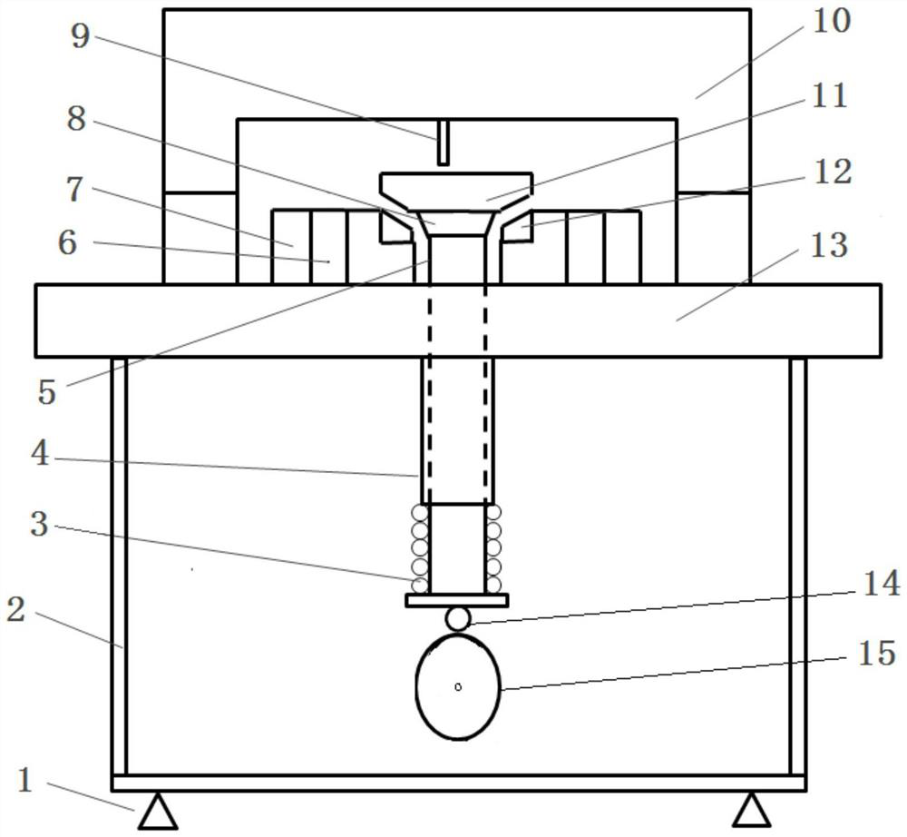
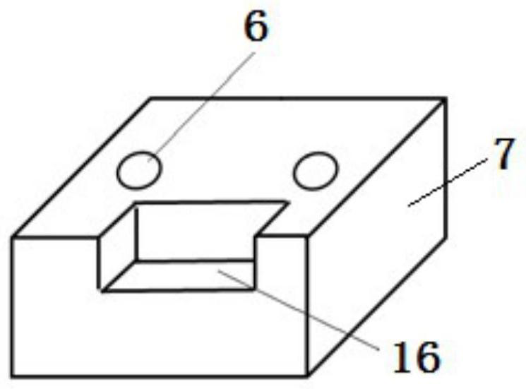
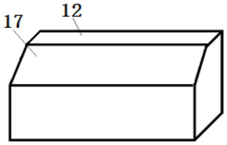
[0033] Such as figure 1 and Figure 4 As shown, a wide temperature range high-speed impact wear testing machine provided by the present invention includes a test frame, a working platform 13 is arranged above the test frame; a high-temperature furnace 10 is arranged on the working platform 13, and an impact test module is arranged in the high-temperature furnace 10 , the impact test module includes two oppositely arranged test block mounts 7, the test block mounts 7 are connected to the working platform 13, the test block mounts 7 are provided with mounting grooves 16, and the test block 12 is installed in the mounting grooves 16, and the test block 12 is provided with a threaded hole 6. When in use, the test block 12 is installed in the installation groove 16 by bolts. The impact block mounting seat 8 is slidably arranged between the two test block mounting seats 7. The impact block mounting seat 8 is disassembled and connected with Impact block 11, the driving mechanism is ...

Embodiment 2

[0043] Such as Figure 5 As shown, on the basis of Example 1, the present invention provides a wide temperature range high-speed impact wear tester, wherein the cam 15 is arranged on one side of the lower end of the ejector rod 5, and also includes a connecting rod 19 whose middle position rotates Erected on the test stand, both ends of the connecting rod 19 are connected with rollers 14, one of which is in contact with the lower end of the push rod 5, and the other roller 14 is in contact with the contour surface of the cam 15.

[0044] A lever-type connecting rod is designed and installed between the cam 15 and the ejector rod 5, and the leverage principle is used to reduce the requirement for the torque power of the servo motor. 14 moves down, the roller 14 on the other side moves up, and the ejector rod 5 moves upwards under the action of the connecting rod 19. The rod 5 moves down under the active force of the spring, and the impact block 11 collides with the test block ...


PUM


Abstract

The invention relates to a wide-temperature-range high-speed impact wear testing machine which comprises a test rack, a working platform, a high-temperature furnace and an impact test module, the working platform is arranged above the test rack, the high-temperature furnace is arranged on the working platform, the impact test module is arranged in the high-temperature furnace, the impact test module comprises a test block mounting seat, and a test block is mounted on the test block mounting seat. The impact block mounting seat is arranged between the two test block mounting seats in a sliding manner, the impact block mounting seat is detachably connected with an impact block, and the output end of the driving mechanism is connected with the impact block mounting seat and is used for driving the impact block mounting seat to reciprocate up and down. A test block mounting seat and an impact block mounting seat are arranged, so that mounting, dismounting and subsequent upgrading are facilitated, test materials can be selected and replaced at will, surface-surface contact impact wear under the condition that the temperature is larger than 0 degree and smaller than 90 degrees can be tested, the impact wear performance of the materials at the high temperature can be truly tested, and research on impact wear behavior rules is facilitated.

Description

technical field [0001] The invention relates to the technical field of material impact wear testing, in particular to a wide temperature range high-speed impact wear testing machine. Background technique [0002] When the internal combustion engine is working, the valve will periodically reciprocate at a certain frequency (valve opening and closing) with the intake and exhaust strokes of the engine, and periodically contact and collide with the valve seat on the cylinder head to ensure the periodic sealing of the combustion chamber and ventilation, as the engine speed and combustion chamber explosion pressure continue to increase, the frequency and impact force of the contact and collision between the valve and the valve seat will increase. Long-term high-temperature contact and collision will cause wear of the valve and valve seat, and the dimensional accuracy Decline, the two are not closely matched, and eventually cause the combustion chamber to leak, reduce the thermal e...

Claims


Application Information

Patent Timeline
Patent Type & Authority Applications(China)
IPC IPC(8): G01N3/56G01N3/32G01N3/02
CPCG01N3/56G01N3/32G01N3/02
Inventor 武岳李建平杨忠马志军郭巧琴梁民宪
Owner XIAN TECH UNIV
Why Eureka
Try Eureka