Reciprocating cutter

A technology of cutting tools and reciprocating rods, which is applied to manufacturing tools, metal sawing equipment, metal processing equipment, etc., can solve the problems of limiting the movement range of the guide wheel bracket, limiting the movement range of the guide wheel bracket, etc., and achieves flexible use and structure. Simple, compact and quick-to-operate effects

Active Publication Date: 2010-03-03
POSITEC POWER TOOLS (SUZHOU) CO LTD
View PDF1 Cites 4 Cited by
  • Summary
  • Abstract
  • Description
  • Claims
  • Application Information

AI Technical Summary

Problems solved by technology

[0005] At the same time, on a jigsaw with a compact structure, pulling the guide wheel away from the saw blade will face such a problem. The knife lifting mechanism of the jigsaw will limit the range of motion of the guide

Method used


Image

  • Reciprocating cutter
  • Reciprocating cutter
  • Reciprocating cutter

Examples


Embodiment Construction

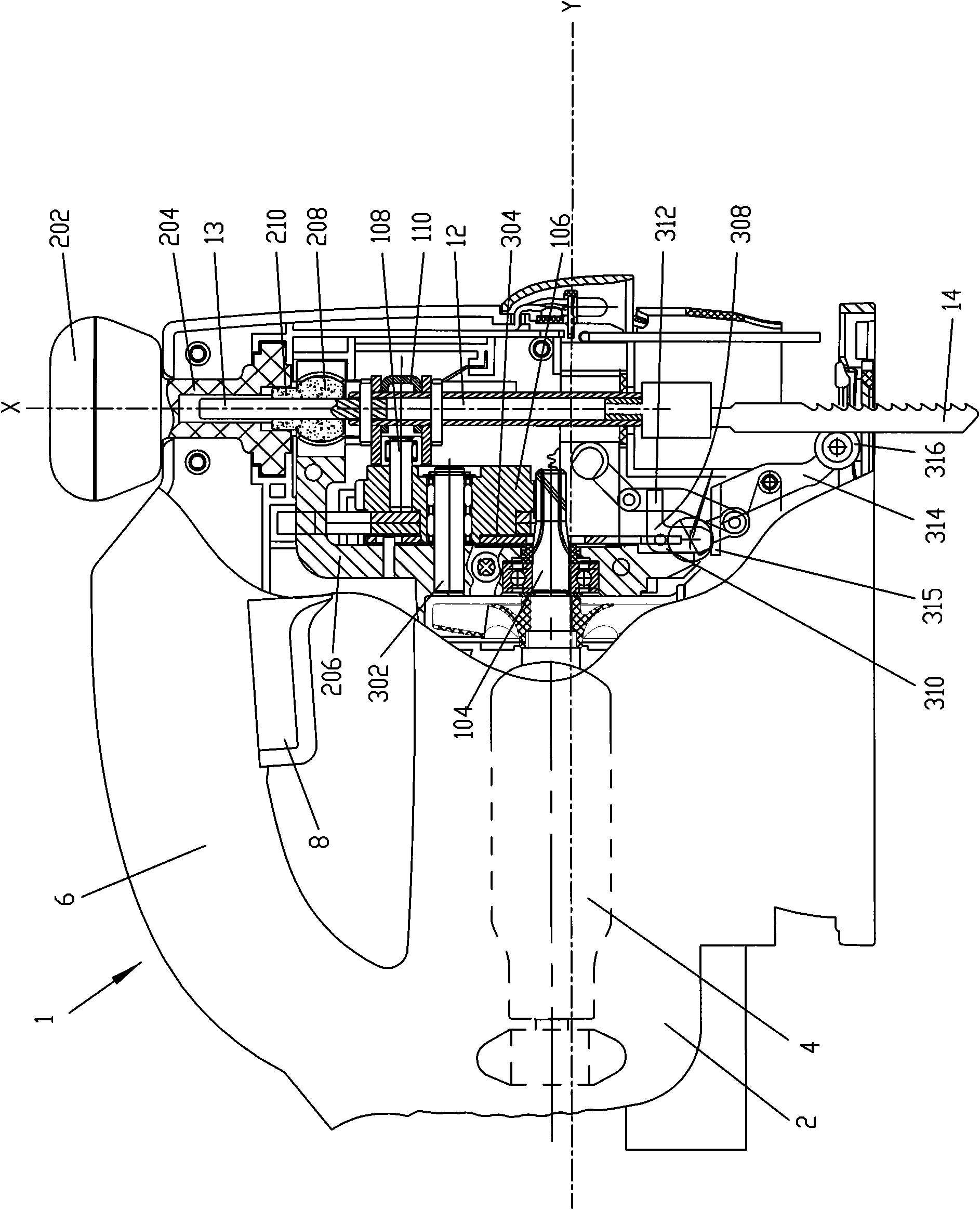
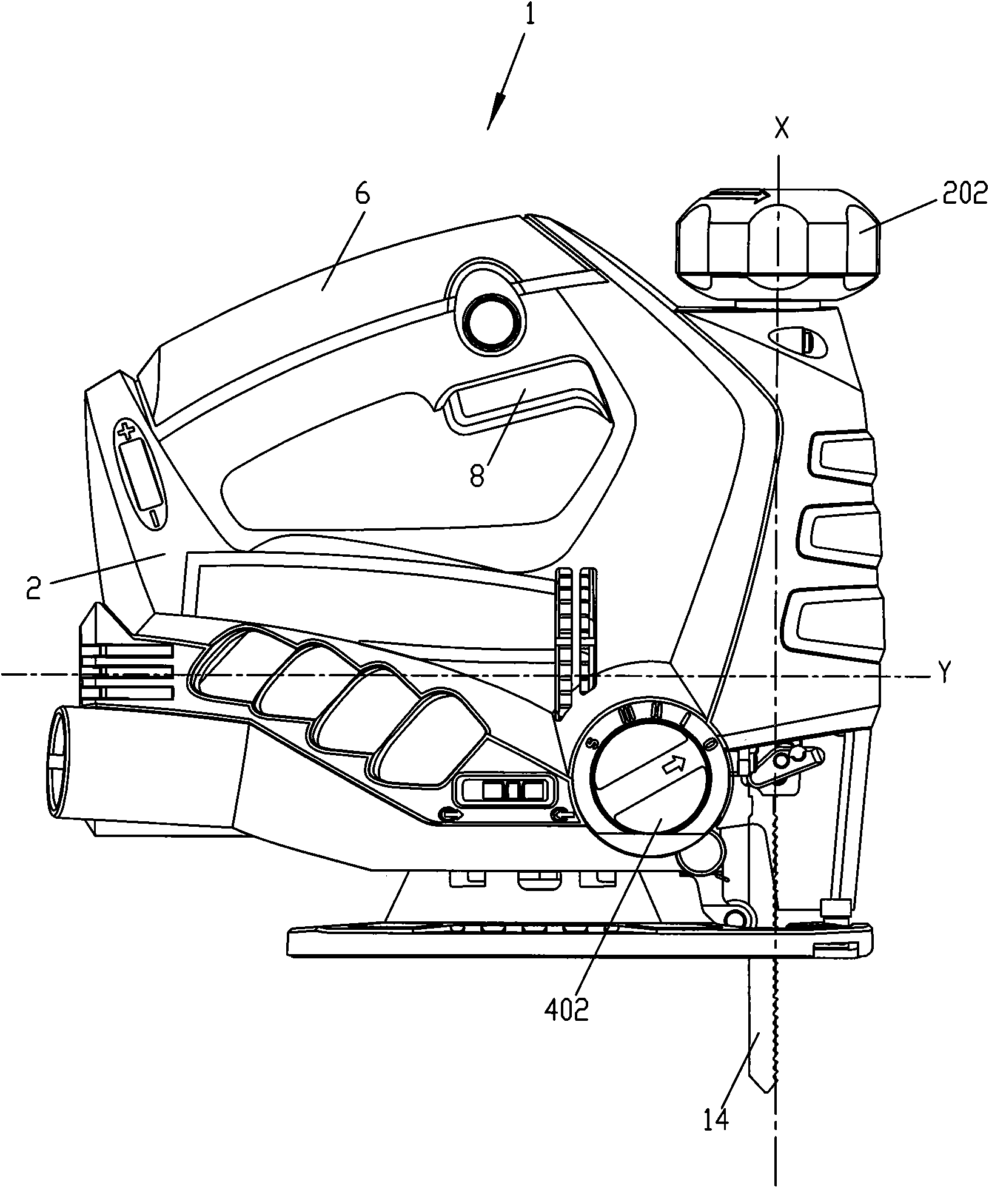
[0048] The preferred embodiment of the reciprocating cutting tool of the present invention is a jig saw. Such as figure 1 As shown, the left side of the jig saw 1 of this embodiment is defined as the rear of the jig saw 1, the right side is defined as the front, the upper side is defined as the upper side, and the lower side is defined as the lower side. The jig saw 1 has a reciprocating axis X extending in the up-down direction and a housing longitudinal axis Y extending in the front-rear direction, and the axis X and the axis Y are perpendicular to each other.

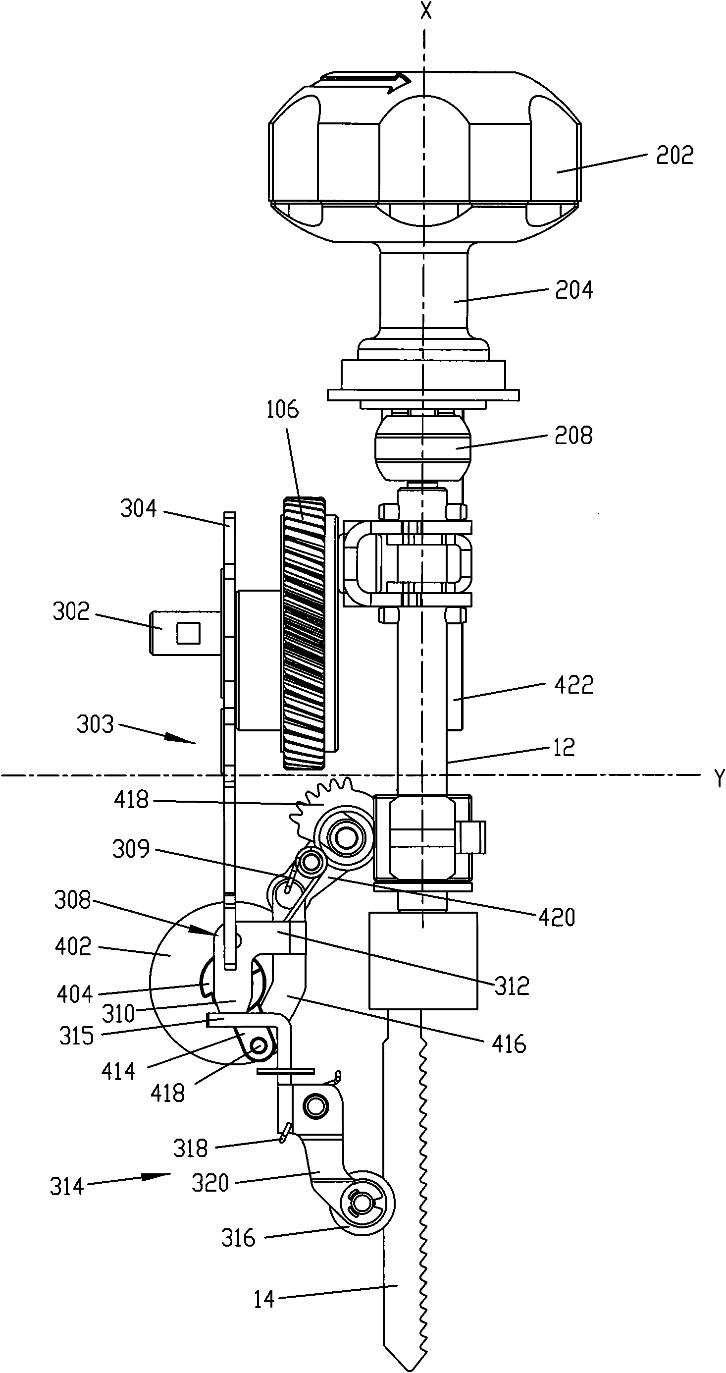
[0049] Such as figure 1 The jig saw 1 includes a housing 2, and a power source is fixedly arranged in the housing 2. In this embodiment, it is preferably a motor 4. The motor 4 is connected to and rotationally drives the main shaft 104. One end of the main shaft 104 is connected to the motor 4, and the other end A gear is formed, and the gear meshes with the outer peripheral surface of the large gear 106. The large gea...


PUM


Abstract

The invention relates to a reciprocating cutter which comprises a shell, a motor, a reciprocating mechanism, a cutter lifting component and a transmission component, wherein the motor is arranged in the shell; the reciprocating mechanism is arranged in the shell; the reciprocating mechanism comprises a reciprocating lever and a saw blade, wherein the reciprocating lever is driven by the motor to move in a reciprocating way along the axis X opposite to the shell, and the saw blade is connected with the reciprocating lever; the cutter lifting component is arranged in the shell; the transmissioncomponent is arranged between the cutter lifting component and the reciprocating mechanism; the cutter lifting component drives the transmission component to press the saw blade along the cutting direction of the saw blade; and the cutter lifting component comprises a connecting plate and a cutter lifting plate, wherein the connecting plate is driven by the motor to move opposite to the shell, and the cutter lifting plate is movably connected with the connecting plate.

Description

Technical field [0001] The invention relates to a reciprocating cutting tool. In particular, it relates to a reciprocating cutting tool with an optimized knife lifting component. Background technique [0002] As a power tool, a reciprocating cutting tool is widely used and familiar to those skilled in the art. It includes a housing, a motor installed in the housing, and a saw blade driven by the motor to reciprocate relative to the housing to cut the workpiece. . Jig saws and reciprocating saws are all reciprocating cutting tools. [0003] Many jig saws have the function of lifting the blade. Due to a lifting force that drives them to swing, the jig saw blade can slightly swing in a direction perpendicular to its reciprocating cutting. Since the saw blade is given a force to point to the workpiece, the knife lifting function can significantly improve the cutting efficiency. At the same time, some jig saws also have a saw blade rotation function, which allows the saw blade to ro...

Claims


Application Information

Patent Timeline
IPC IPC(8): B23D49/16B23D51/20B23D51/10B23D51/16
Inventor 段家利
Owner POSITEC POWER TOOLS (SUZHOU) CO LTD
Why Eureka
Try Eureka