
Transmission

A transmission and force technology, applied in friction transmission, belts/chains/gears, mechanical equipment, etc., can solve the problems of incompatibility of end cams, insufficient pressing force, excessive pressing force, etc. Insufficient pressure, low number of parts, simple construction effect

Inactive Publication Date: 2010-03-03
JATCO LTD
View PDF5 Cites 5 Cited by
  • Summary
  • Abstract
  • Description
  • Claims
  • Application Information

AI Technical Summary

Problems solved by technology

However, when the driving radius of input and output changes in various ways due to the gear ratio, "necessary pressing force ≠ output torque (different gear ratio)", the end cam provided on the output side cannot respond
That is, there is a problem that when the end face cam is applied to a transmission whose input and output drive radius varies in various ways due to the speed ratio, the pressing force on the speed increasing ratio side is insufficient and the pressing force on the reducing ratio side is excessive, resulting in poor durability. sexual deterioration

Method used

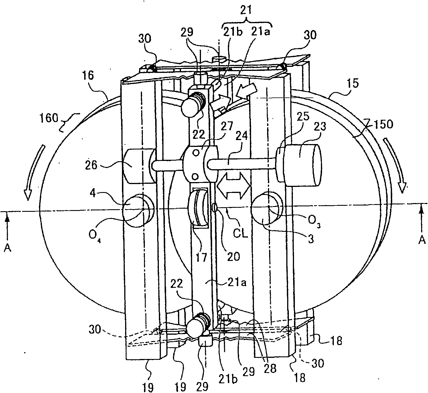
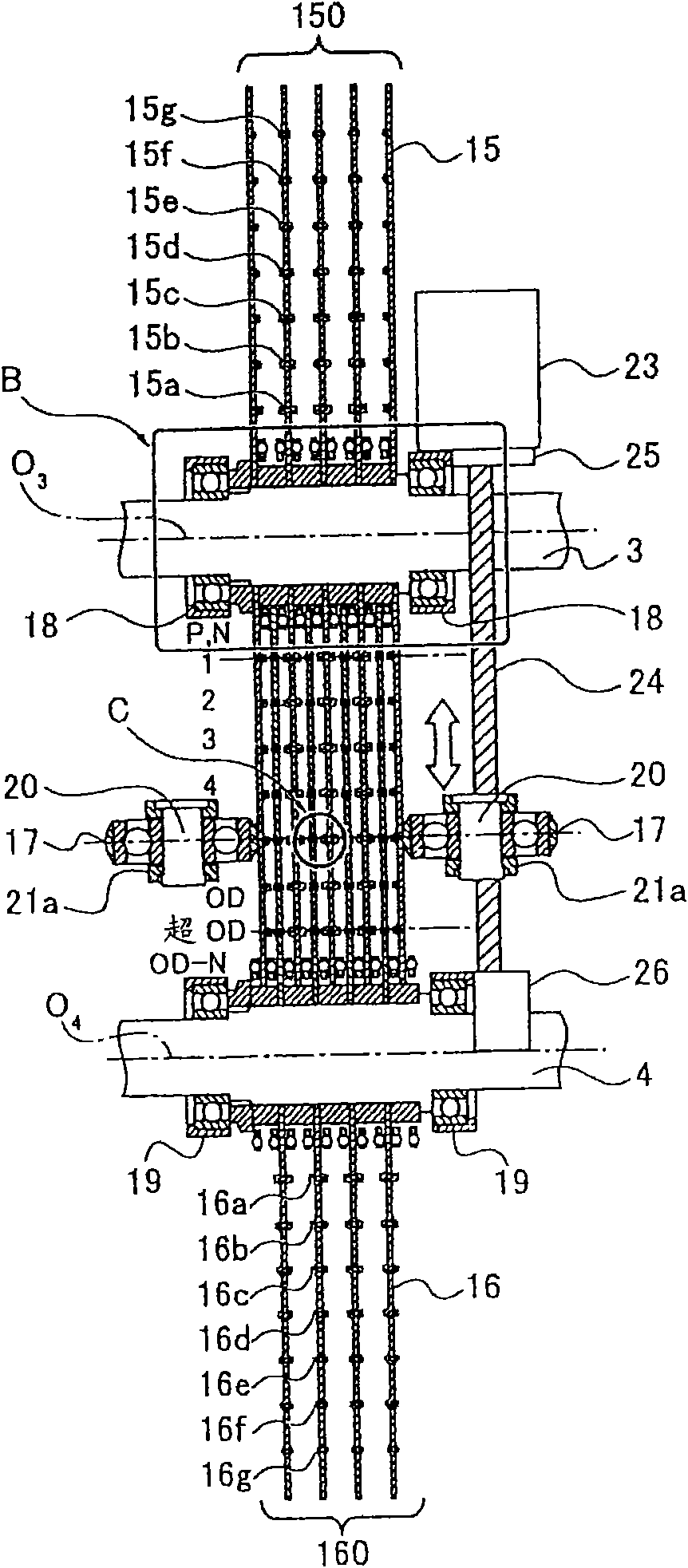

Image

  • Transmission
  • Transmission
  • Transmission

Examples


Embodiment 1

[0062] First, the configuration will be described.

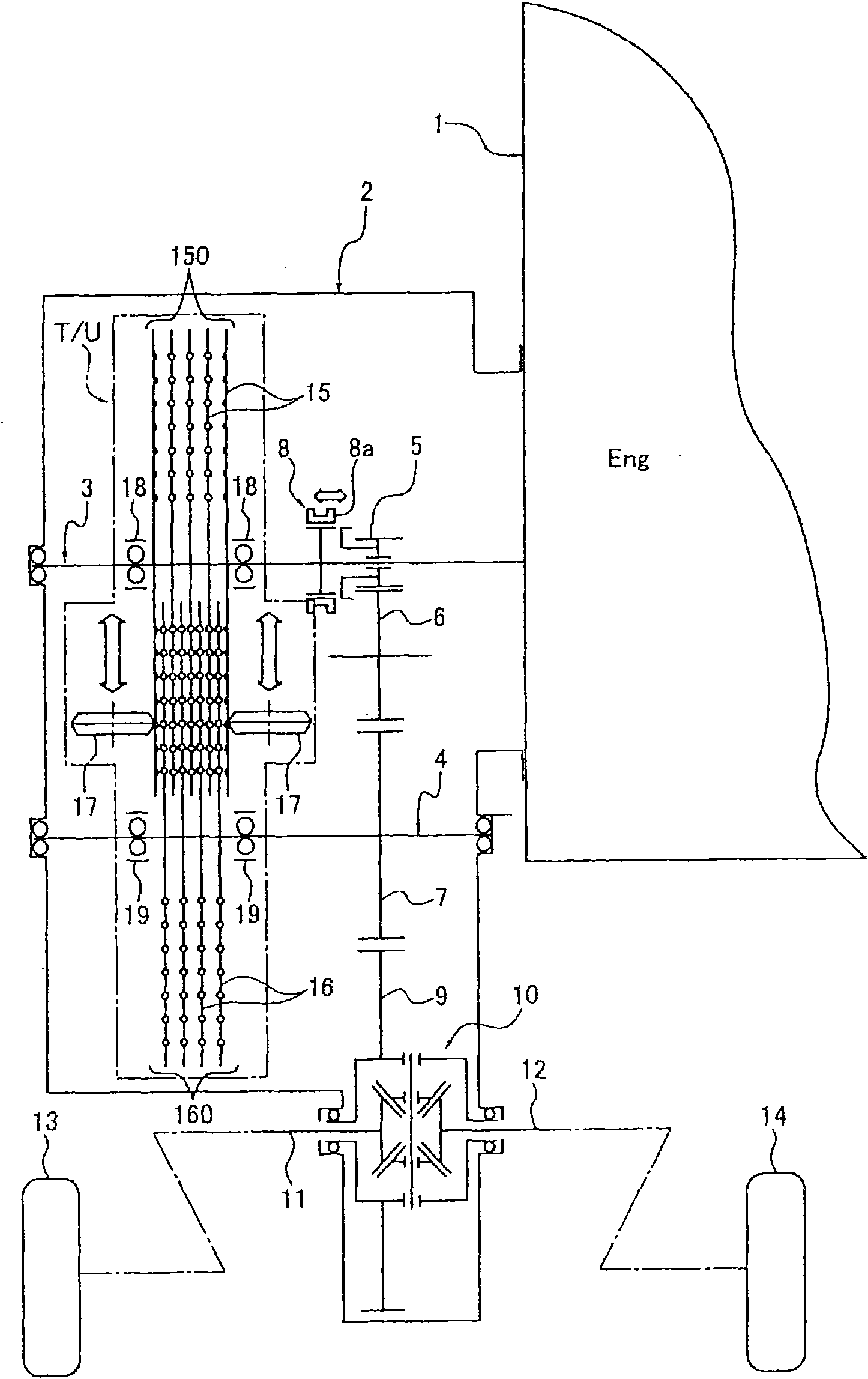
[0063] figure 1 It is an overall schematic diagram showing the automatic transmission system for a vehicle to which the multi-disk multi-stage transmission unit T / U (an example of the transmission) of the first embodiment is applied.

[0064] The automatic transmission system for vehicles that has been applied to the multi-disk multi-stage transmission unit T / U of embodiment 1 is as follows: figure 1 As shown, it has: engine 1 (prime mover), transmission case 2, input shaft 3, multi-disk multi-stage transmission unit T / U, output shaft 4, reverse gear 5, reverse intermediate gear 6, output gear 7, synchronous Mechanism 8, final reducer 9, differential gear unit 10, left and right drive shafts 11, 12, left and right drive wheels 13, 14.

[0065] The above-mentioned multi-disk multi-stage transmission unit T / U has: a main disc group 150 composed of a plurality of input discs 15, a sub-disc group 160 composed of a plurality ...


PUM


Abstract

The invention relates to a transmission capable of realizing low cost, light weight and compaction, having a speed changing function with setting freedom degree and high variation ratio containing speed increasing ratio and a clutch function for switching the transference / truncation of the torque moment, and capable of realizing durability improvement by application of optimum clamp press force corresponding to the variation ratio. The inventive transmission has a circular plate shaped input disk installed on an input shaft; a circular plate shaped output disk installed on an output shaft; a pair of pressure rollers provided to be movable along a two-axes connecting line of the axes of the input and output shafts, within a disk overlapping area that the input and output disks overlap witheach other. The pressure roller pair is configured to sandwich the input and output disks at a position corresponding to a required transmission ratio, wherein the pressure roller pair includes a guide plate and a cam follower which regulate the acting force of the disk spring applied as the clamping press force of the two disks to obtain the optimum push clamp force corresponding to the transmission condition.

Description

technical field [0001] The present invention relates to a transmission suitable for a vehicle transmission or the like, and relates to a friction transmission mechanism that utilizes elastic deformation of a thin disc-shaped disk to contact a drive transmission portion. Background technique [0002] Conventionally, as a transmission using discs, there is known a structure called a Bayer type transmission that is provided with a friction transmission mechanism composed of a plurality of conical discs and a plurality of flanged discs (for example, refer to Patent Document 1). image 3 and Figure 4 ). [0003] The Bayer type transmission transmits the power input to the input shaft to a plurality of spline shafts through gears, and then distributes the power equally to a plurality of conical disk sets. The conical disc groups are alternately clamped between the plurality of flanged disc groups arranged in the center, and are pressed against by the crimping force of the spring...

Claims


Application Information

Patent Timeline
Patent Type & Authority Applications(China)
IPC IPC(8): F16H15/22
CPCF16H15/46F16H15/14F16H15/18F16H15/22
Inventor 丹下宏司
Owner JATCO LTD
Learn More