Heating cooking device

A cooker and heater technology, which is applied to electric heating fuels, lighting and heating equipment, heating fuels, etc., can solve the problems of inability to obtain, non-uniform hot air circulation, and inability to prevent water droplets, and achieves the promotion of homogenization, Seeking the effect of production cost

Active Publication Date: 2010-03-03
TOSHIBA LIFESTYLE PROD & SERVICES CORP
View PDF3 Cites 14 Cited by
  • Summary
  • Abstract
  • Description
  • Claims
  • Application Information

AI Technical Summary

Problems solved by technology

Therefore, it is difficult to obtain a suitable mixed state of hot air, and it is impossible to obtain uneven hot air circulation and uniform heating distribution in the box.
[0011] And in the heating cooker that has steam supply mechanism, the situation that steam adheres to the wall surface of the oven casing and becomes water drop is in the majority, especially, if produce water drop on the top surface surface of oven casing, then water drop falls from top surface, and adheres to In food, may affect cooking results
In this case, in the heating cooker of the above-mentioned Patent Document 2, although countermeasures have been considered for the recovery of the water droplets on the back panel of the oven box, it is not possible to prevent the water droplets from falling on the food from the top surface.
In addition, although the structure described in Patent Document 3 is effective in preventing fogging or dew condensation on the see-through window of the door, it cannot prevent water droplets from falling on the food from the top surface.

Method used


Image

  • Heating cooking device
  • Heating cooking device
  • Heating cooking device

Examples


no. 1 approach

[0050] Hereinafter, refer to the description of the first embodiment of the present invention Figure 1 to Figure 3 Be explained.

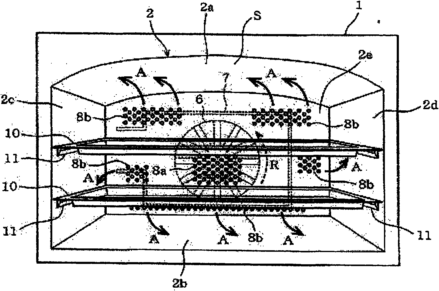
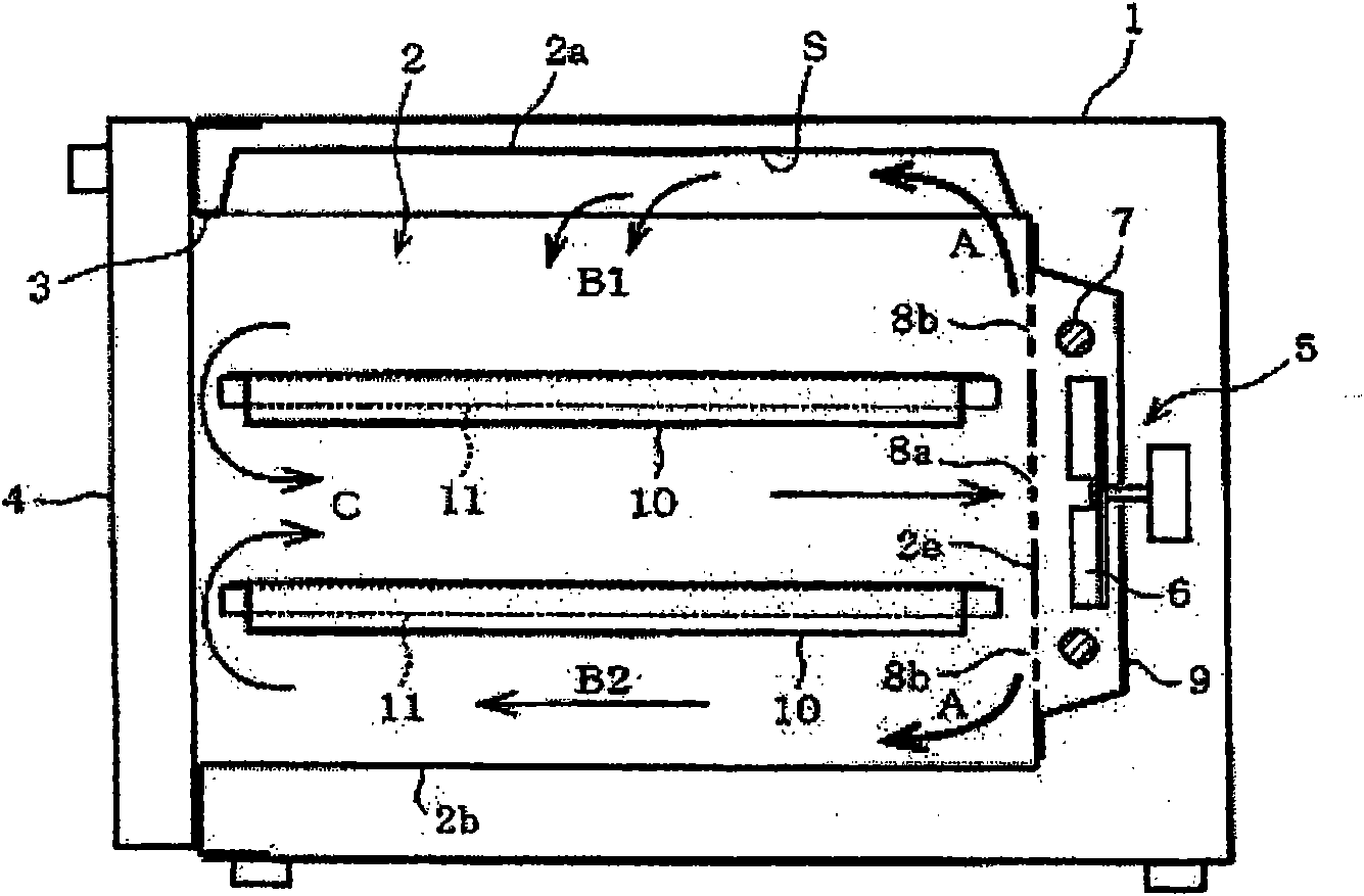
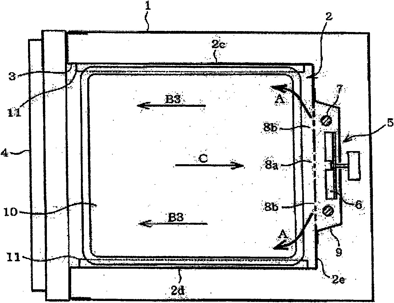
[0051] figure 1 It is the front view of the heating cooker in the state that took off the front door, figure 2 It is a longitudinal sectional side view showing the cross-sectional structure of the substantially central part except the door, image 3 Similarly, it is a cross-sectional plan view which shows the cross-sectional structure of the substantially central part except a door, and demonstrates the whole result of a heating cooker based on these figures.

[0052] In the inside of the rectangular box-shaped housing 1 that forms the outer contour, an open front, that is, a box-shaped oven box body 2 is provided on the front surface, and the front surface opening 3 is opened and closed in a rotatable manner. Door 4. In addition, as the peripheral wall forming the oven box body 2, it includes a top wall 2a, a bottom wall 2b, a left side wall...

no. 2 approach

[0095] With respect to above-mentioned embodiment, Figure 6 to Figure 10 The second embodiment of the present invention is shown, and the parts substantially the same as those of the above-mentioned first embodiment are given the same reference numerals and their descriptions are omitted, and the different points will be described.

[0096] Figure 6 It shows the longitudinal section front view structure of the plane heater and the heater platen, Figure 7 It is figure showing heating cooker which omitted door from front view, Figure 8 The longitudinal section side structure of the heating cooker 1 is shown. Figure 9 It is a figure which shows the 2nd embodiment of the heating cooker which has the surface heater effective for grill cooking, Figure 10 It is a perspective view of a flat heater platen.

[0097] Collar parts (flange parts) 21a and 21b are formed on the left and right side walls 2c and 2d upper ends of the oven box 2, and flange parts 22a and 22b are also f...

no. 3 approach

[0114] With respect to above-mentioned embodiment, Figure 11 to Figure 14The third embodiment of the present invention is shown, and the parts substantially the same as those of the above-mentioned first embodiment are given the same reference numerals and their explanations are omitted, and the different points will be described.

[0115] Figure 11 , 12 A third embodiment of a heating cooker having a flat heater 14 effective for roasting and cooking is shown, wherein, Figure 11 It is a longitudinal front view showing the schematic structure of the heating cooker; Figure 12 It is an external perspective view of the oven body 2 viewed from above.

[0116] The above-mentioned planar heater 14 is generally provided on the outer wall surface side of the top wall 2a in a closely adhered state. Therefore, in order to form it into a flat shape, for example, a coil for a heater is wound on a flat mica plate and sandwiched from both surfaces by the mica plate.

[0117] However...


PUM


Abstract

The present invention provides a heating cooking device, the hot air blown from a hot air circling unit can be evenly circled in a oven body and seek to equalization heating distribution. In order toheat the food contained in the oven body (2) by the hot air oven, the heating cooking device has a hot air circling unit comprising a hot air heater (7) and a hot air fan (6), wherein a curve shape portion (S) having a depressed inner side is arranged at least one of peripheral surface of the peripheral surfaces of the oven body (2) blowing hot air from the hot air circling unit.

Description

technical field [0001] The present invention relates to a heating cooker capable of cooking food by heating in a hot air oven. Background technique [0002] Conventionally, in order to broaden the types of heating and cooking of foods, heating cookers having a plurality of heating mechanisms have been provided. For example, a heating mechanism including a hot air circulation unit for heating food in a hot air oven, a magnetron (magnetron) for microwave (high frequency) heating of food, and a flat heater for baking and cooking is widely popularized. cooker. [0003] Wherein, the above-mentioned hot air circulation unit is used as a heating mechanism, for example, is arranged on the peripheral wall side of the innermost part of the oven box, is configured to include a hot air heater and a hot air fan, and repeats the following cycle: from the hot air circulation unit to the oven box. The hot air blown out is recycled to the hot air circulation unit after heating the food pla...

Claims


Application Information

Patent Timeline
Patent Type & Authority Applications(China)
IPC IPC(8): F24C7/00F24C7/02F24C7/06
Inventor 古田和浩神谷浩美一柳俊成
Owner TOSHIBA LIFESTYLE PROD & SERVICES CORP
Why Eureka
Try Eureka