Three dimensional shape measuring apparatus
A measuring device and three-dimensional shape technology, which is applied in the field of measuring probes, can solve problems such as the deterioration of Z-axis moving straightness, the inability to measure inclination and eccentricity, and the inability to measure the back of the watch, etc., and achieve the effect of light probe, simple structure and easy manufacture
- Summary
- Abstract
- Description
- Claims
- Application Information
AI Technical Summary
Problems solved by technology
Method used
Image

Examples
no. 1 approach
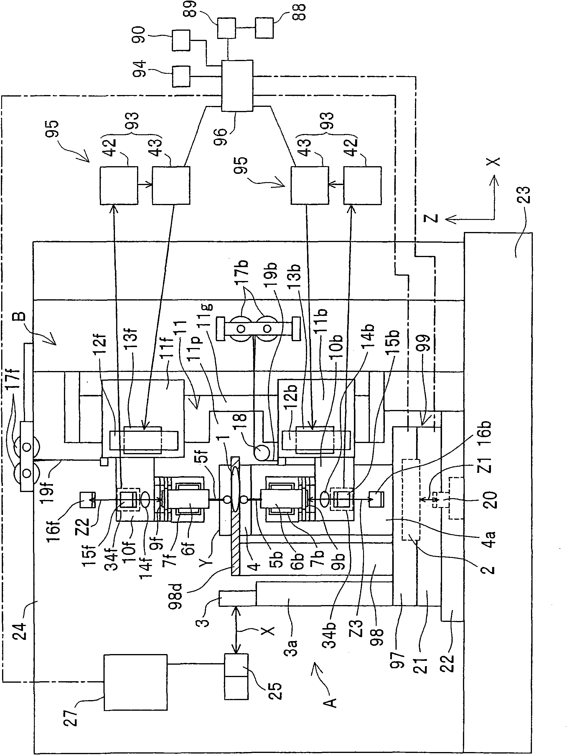
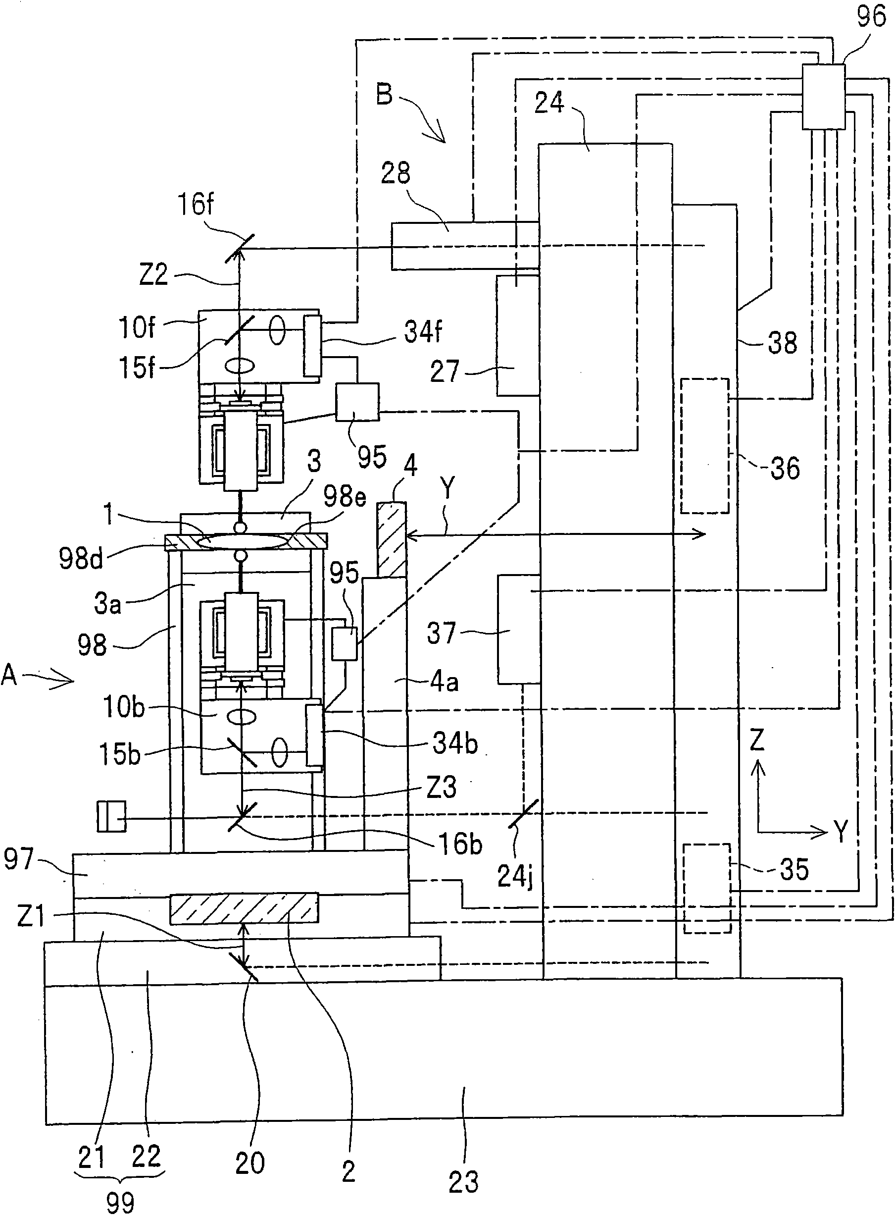
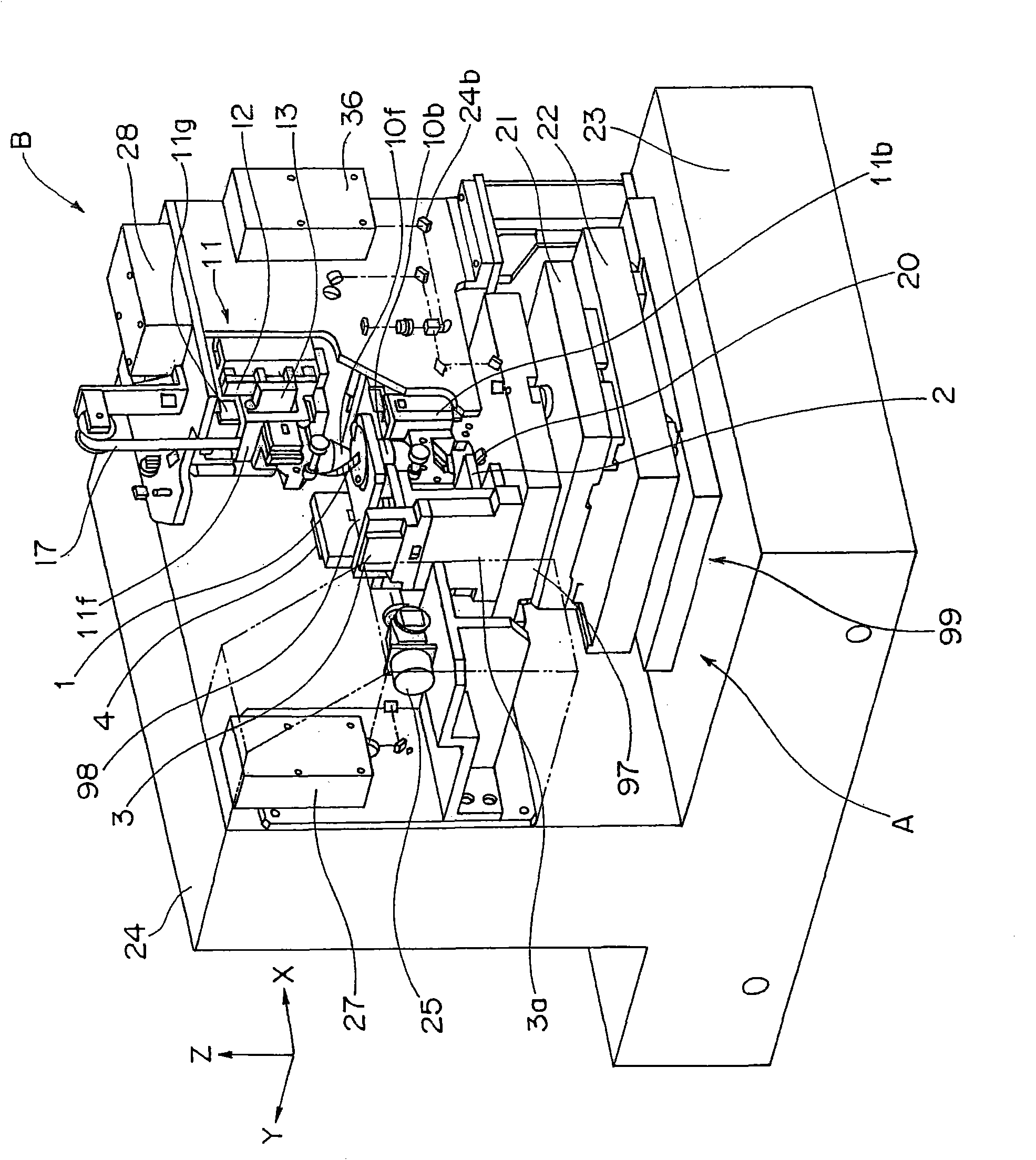
[0140] figure 1 is a front view showing the structure of the three-dimensional shape measuring device in the first embodiment of the present invention, figure 2 From figure 1 Right sectional side view viewed from the right side after the center of is cut, Figure 3A and Figure 3B It is a three-dimensional view and its partial enlarged view.
[0141] The three-dimensional shape measuring device is configured to include: a lower stone platform 23; a side stone platform 24, which is erected and fixed on the back side of the upper surface of the lower stone platform 23; a first unit A, which has measurement object holding members 98, Z Reference mirror (Z direction reference mirror, hereinafter referred to as "Z reference mirror") 2, X reference mirror (X direction reference mirror, hereinafter referred to as "X reference mirror") 3 and Y reference mirror (Y direction reference mirror, hereinafter referred to as "Y Reference mirror ") 4; second unit B, which has at least Z...
no. 2 approach
[0197] In the first embodiment, the structure itself of the large air bearing 11 has been particularly described in detail, however, in the three-dimensional shape measuring device according to the second embodiment of the present invention, the two measuring probes 10f are moved in the Z direction The guide portion along the Z direction of the measuring probe moving device 93 in 10b, that is, the guide rail portion 11g of the large air bearing 11 is constituted by the same processing plane up and down. Specifically, as figure 1 As shown, the guide rail part 11g of the large air bearing 11 is cut off at the left side of the central part in order to prevent mutual interference with the measurement object 1 (see 11p), and the right side of the guide rail part 11g is connected up and down with the surface parallel to the paper surface into one. In addition, since the guide rail portion 11g of the large air bearing 11 is a square prism, it has four faces, and these are formed by...
no. 3 approach
[0200] In the first and second embodiments, it was described that the directions of the coordinate axes of the front and back of the measurement object 1 can be completely aligned. However, it is actually extremely difficult to align the stylus 5f and 5b on the same Z-axis with an accuracy of less than 0.1 micron.
[0201] Therefore, in the three-dimensional shape measuring device in the third embodiment of the present invention, if Figure 4A and Figure 3D As shown, a reference ball 91 with good sphericity is supported in the through hole 98e of the measuring object holding plate part 98d of the measuring object holding member 98, and the reference ball 91 is supported from the surface (upper surface or front surface) by the stylus 5 and 5b. The supported reference ball 91 is measured against the back surface (lower surface or rear surface). As the reference ball 91, those with a degree of sphericity of 30 nm can be relatively easily manufactured. In addition, in the thro...
PUM
 Abstract
Description
Claims
Application Information
 - R&D Engineer
- R&D Manager
- IP Professional
- Industry Leading Data Capabilities
- Powerful AI technology
- Patent DNA Extraction
Browse by: Latest US Patents, China's latest patents, Technical Efficacy Thesaurus, Application Domain, Technology Topic.
© 2024 PatSnap. All rights reserved.Legal|Privacy policy|Modern Slavery Act Transparency Statement|Sitemap