
A reflective lyot filter based on circular polarizer

A filter and circular polarizer technology, applied in the field of optical signal processing, can solve the problems of high cost and difficult adjustment, and achieve the effect of small environmental impact and half cost

Active Publication Date: 2018-01-05
HUAZHONG UNIV OF SCI & TECH
View PDF3 Cites 0 Cited by
  • Summary
  • Abstract
  • Description
  • Claims
  • Application Information

AI Technical Summary

Problems solved by technology

[0005] Aiming at the defects that a single Lyot filter needs two polarizers in the prior art, and the alignment of polarizer angles is required, the cost is high, and adjustment is difficult, the purpose of the present invention is to solve the above technical problems

Method used


Image

  • A reflective lyot filter based on circular polarizer
  • A reflective lyot filter based on circular polarizer
  • A reflective lyot filter based on circular polarizer

Examples


Embodiment 1

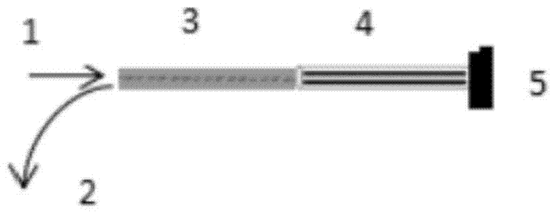
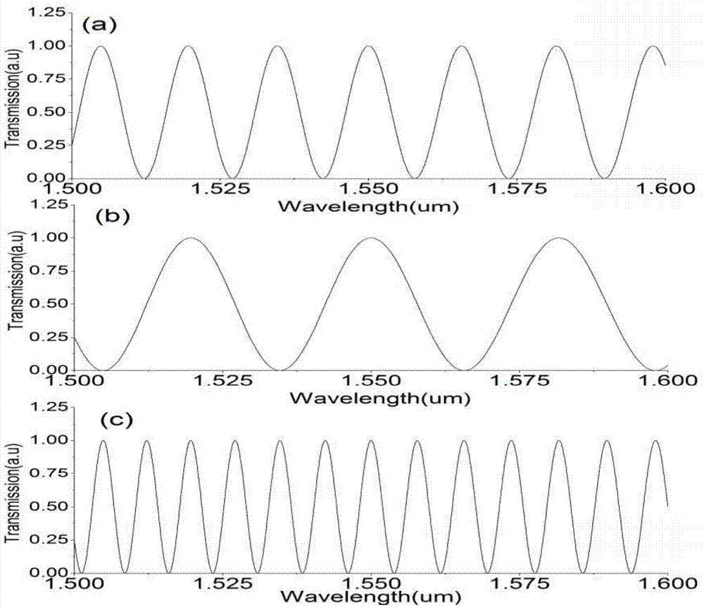
[0023] The incident light enters the circular polarizer CP, and the incident end of the birefringent optical fiber (PM optical fiber) is connected with the outgoing end of the circular polarizer. The end of the birefringent fiber is coated with a highly reflective coating. The length of the birefringent fiber is L, and the difference between the slow axis and the fast axis refractive index is Δn=7.75×10 -4 . The light wave is reflected by the reflective device at the end of the birefringence (such as an optical ring mirror, a high-reflection film, etc.), and finally exits the circular polarizer. Fig. 1 shows the schematic diagram of the structure of Example 1. Fig. 2(a), (b), (c) show the normalized transmission spectrum diagram of exit port 3 under the condition of birefringent fiber length L=0.1 meter, 0.05 meter and 0.2 meter.

Embodiment 2

[0025] This example is a schematic diagram of a three-stage cascade of reflective Lyot filters. The birefringent optical fiber PMFiber3 is used to connect the circular polarizers CP3 and CP2, the birefringent optical fiber PMFiber2 is used to connect the CP2 and CP1, and the PMFiber1 is used to connect the CP1 and the reflection device. The length of PMFiber1 is L1=0.2 meters, the length of PMFiber2 is L2=0.4 meters, and the length of PMFiber3 is L3=0.2 meters. The difference between the slow axis refractive index and the fast axis refractive index of the birefringent fiber Δn=7.75×10 -4 . Any one or several birefringent fibers have the same length, and the length is half or twice the length of other birefringent fibers (other birefringent fibers are also the same length), or all birefringent fibers are the same length, and the birefringent fibers are slow and fast Axial refractive index difference greater than 10 -4 , a very high side-mode suppression ratio can be obtained...


PUM


Abstract

The invention discloses a reflecting Lyot filter based on ideal circular polarizers and belongs to the field of optical fiber communication. In the prior art, most of Lyot filters are transmission type filters, a single Lyot filter requires two polarizers, the angles of the polarizers are required to be aligned, the cost is high, and the polarizers are difficult to adjust. According to the filter, incident light enters each birefringence fiber through the corresponding fiber type circular polarizer, the tail part of each birefringence fiber is connected with a reflection device such as a high reflecting film, a light-ring-shaped mirror, a Faraday rotating mirror and the like, the incident light is emitted out from the starting end of each birefringence fiber after being reflected and then passes through the corresponding circular polarizer at the incident end, then reflection light is detected, the cost is low, adjustment and alignment of light paths are not required, and the reflecting Lyot fiber is less influenced by the environment.

Description

technical field [0001] The invention belongs to the field of optical signal processing, and more specifically relates to a structure of a Lyot filter based on an ideal circular polarizer. Different from the conventional transmission Lyot, the invention is an all-fiber reflective filter. Background technique [0002] The Lyot filter is a polarization interference filter proposed by Bernard Lyot in 1933. Its basic structure is to place a section of birefringent medium between two parallel polarizers, and the angle between the optical axis of the polarizer and the fast axis or slow axis of the birefringent medium is 45°. Then multiple Lyot filters are cascaded, named as filter. [0003] Lyot filters have been widely used in spectral imaging, optical communication, lasers and other fields. However, most of Lyot's filters are based on bulk devices. The disadvantage of bulk devices is that it requires careful alignment and adjustment of the optical path, and is susceptible t...

Claims


Application Information

Patent Timeline
Patent Type & Authority Patents(China)
IPC IPC(8): G02B27/28
CPCG02B27/288
Inventor 舒学文杜岳卿
Owner HUAZHONG UNIV OF SCI & TECH
Learn More