Projection type video display apparatus

A technology of image display and projection, applied in projection devices, image communication, television, etc., can solve problems such as damage, poor impact resistance of projection lens, adverse effects on projection performance, etc., and achieve the effect of improving operability, simple operation and simple structure

Inactive Publication Date: 2010-03-03
SANYO ELECTRIC CO LTD
View PDF2 Cites 0 Cited by
  • Summary
  • Abstract
  • Description
  • Claims
  • Application Information

AI Technical Summary

Problems solved by technology

[0005] When the image is not projected in this type of projection display device, the projection performance will be adversely affected due to the adhesion of dust, etc., and the intrusion from the gap, etc., into the glass surface of the projection lens exposed from the opening on the front of the main cabinet.
In addition, the projection lens part is particularly poor in impact resistance, so when the device is moved, it will be damaged by some impacts such as collisions

Method used


Image

  • Projection type video display apparatus
  • Projection type video display apparatus
  • Projection type video display apparatus

Examples


Embodiment 1

[0089] 0031

[0090] Refer below Figure 1 to Figure 4 , Embodiment 1 of the present invention will be described in detail.

[0091] 0032

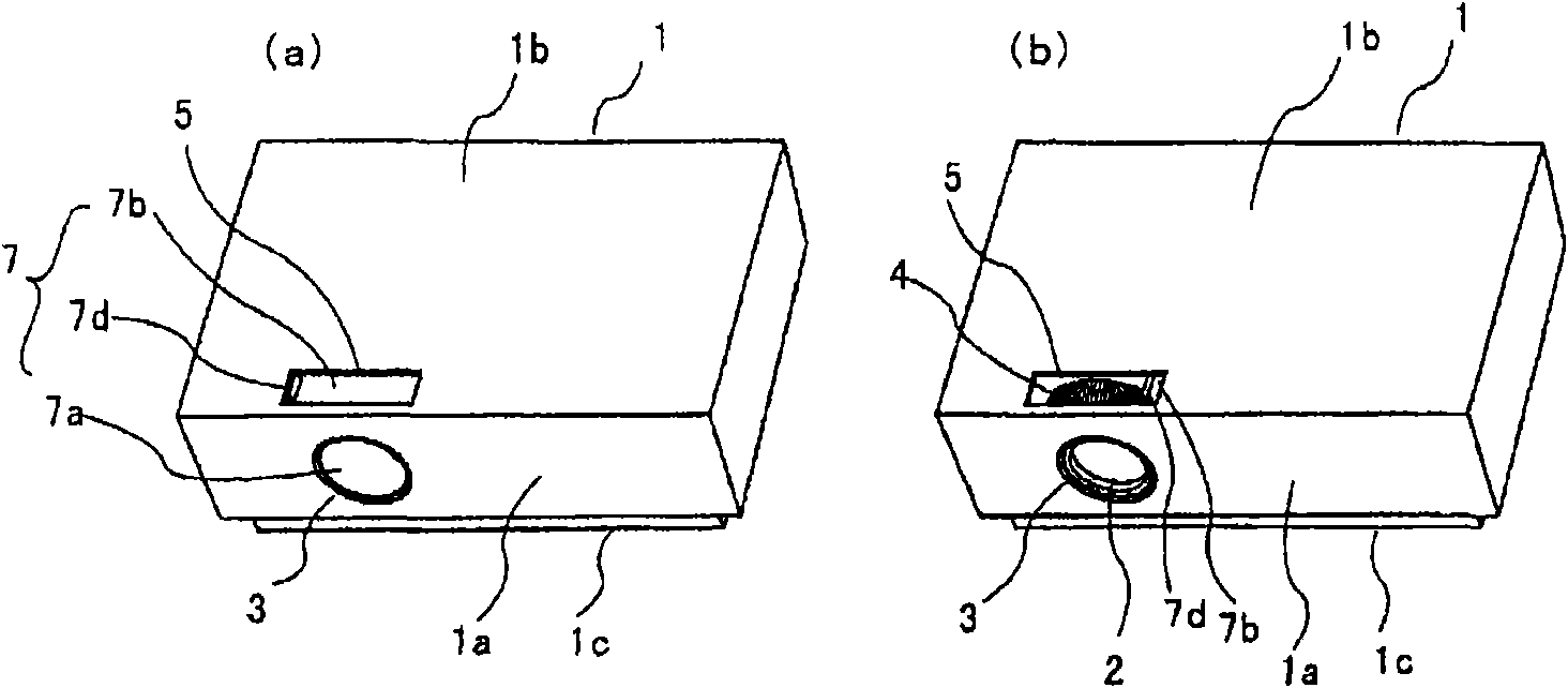
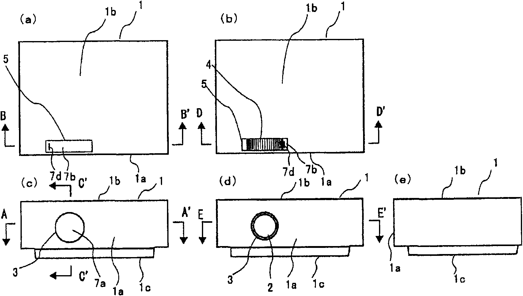
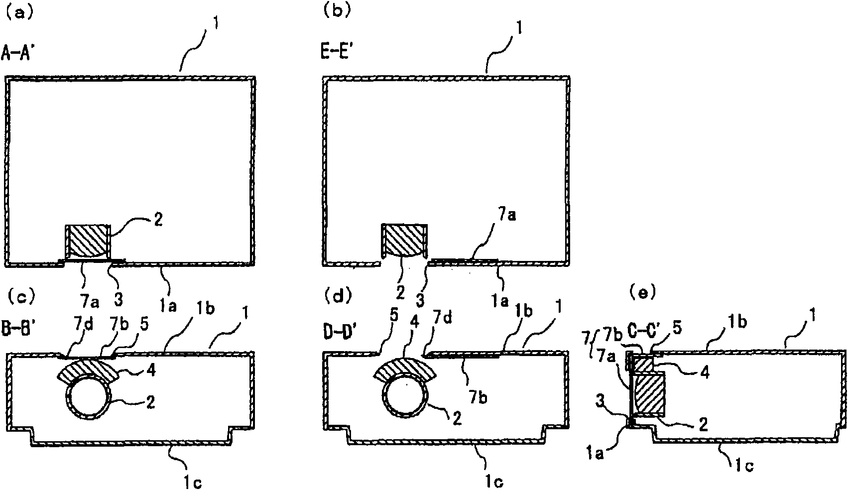
[0092] figure 1 It is a perspective view of an embodiment of a liquid crystal projector as a projection-type image display device of the present invention viewed obliquely from above, figure 1 (a) in (a) shows the state which opened the opening part, and (b) shows the state which opened the opening part. in addition, figure 2 (a) and (b) are plan views, (c) and (d) are front views, (e) is a side view, (a) and (c) show the state with the opening closed, (b) and (d) ) indicates a state where the opening is open. image 3 means the above figure 2 The A-A' profile ~ E-E' profile.

[0093] 0033

[0094] In the main casing 1 of this liquid crystal projector, an opening 3 for the projection lens is formed so that the projection lens 2 is exposed on the left side near the front 1a, and an opening corresponding to the projection lens is ...

Embodiment 2

[0132] 0052

[0133] Figure 5 to Figure 9 Example 2 of the present invention is shown. In addition, the same code|symbol is used for the same component as Example 1, and the description is abbreviate|omitted.

[0134] 0053

[0135] In Embodiment 1, only the slide cover 7 is slid, but in Embodiment 2, the opening 3 for the projection lens and the opening 5 for operation are both opened and closed. The structures of the slide covers 70 are respectively held by holding mechanisms.

[0136] 0054

[0137] Such as Figure 5 As shown, the slide cover 70 made of a nearly L-shaped plate covers the slide cover seat 9 also made of a nearly L-shaped plate, and is configured to be freely slidable relative to the slide cover seat 9 .

[0138] 0055

[0139] Such as Figure 6 As shown, the sliding cover 70 is formed along the sliding direction of the front cover part 70a, and a long groove part 10 with a nearly U-shaped opening; The elastic claw portion 11 protruding perpendicular t...


PUM


Abstract

Provided is a projection-type video display device where a projection lens opening formed in a front face of a body case and an operation opening formed in a surface adjacent to the body case are protected against dust and impact to protect a projection lens portion against them. A projection type video display apparatus having a projection lens opening (3) formed in the front end (1a) of the apparatus and a lend adjustment opening (5) formed in one end adjacent the front end, both openings protected against dust and external mechanical shocks. The projection type video display apparatus is adapted to project an image that is generated by modulating light emitted from a light source based on video signals, through a projection lens unit (2) exposed in the projection lens opening (3). The apparatus comprises lens adjustment members (e.g. adjustment dial 4) for zooming and / or focusing the projection lens unit (2), and a cover mechanism (slide cover 7) for opening and closing the projection lens opening (3) and lend adjustment opening (5).

Description

[0001] This application is a PCT patent application submitted on November 20, 2008 that has entered the Chinese national phase (the Chinese national application number is 200780019280.9, the international application number is PCT / JP2007 / 060046, and the invention name is "projection-type image display device") divisional application. technical field [0002] 0001 [0003] The present invention relates to a projection type video display device such as a liquid crystal projector that modulates light emitted from a light source based on a video signal and projects it through a projection lens exposed through an opening in the front of a main cabinet to display a video. Background technique [0004] 0002 [0005] When no image is projected in this type of projection display device, the projection performance will be adversely affected due to the adhesion of dust and the like and entry from gaps and the like into the glass surface of the projection lens exposed from the opening ...

Claims


Application Information

Patent Timeline
Patent Type & Authority Applications(China)
IPC IPC(8): G03B21/14H04N5/74
Inventor 栗田龙博铃木创千野洋冈崎昌二猿渡俊弘
Owner SANYO ELECTRIC CO LTD
Why Eureka
Try Eureka