
Gradation control method and display device

A technology of grayscale control and display device, applied in static indicators, instruments, etc., can solve the problems of lack of time, long data establishment time, long lighting time, data establishment time, etc., and achieve the effect of suppressing the increase of data establishment time.

Inactive Publication Date: 2010-03-03
MITSUBISHI ELECTRIC CORP
View PDF2 Cites 11 Cited by
  • Summary
  • Abstract
  • Description
  • Claims
  • Application Information

AI Technical Summary

Problems solved by technology

[0019] In recent years, the competition for the number of gray scales is fierce. The more the number of gray scales increases, the more the number of data creation increases, making data creation more time-consuming.
[0020] Even considering complex grayscale control to improve display quality and functionality, the longer it takes to create data, the less time is spent on complex grayscale control
[0021] When connecting multi-level driver ICs, it is necessary to create data for multi-output shares, and the data establishment time is longer than the determined lighting time, and the existing methods show flaws

Method used


Image

  • Gradation control method and display device
  • Gradation control method and display device
  • Gradation control method and display device

Examples


Embodiment approach

[0040] Next, an embodiment example of the present invention will be described with reference to the drawings.

Embodiment approach 1

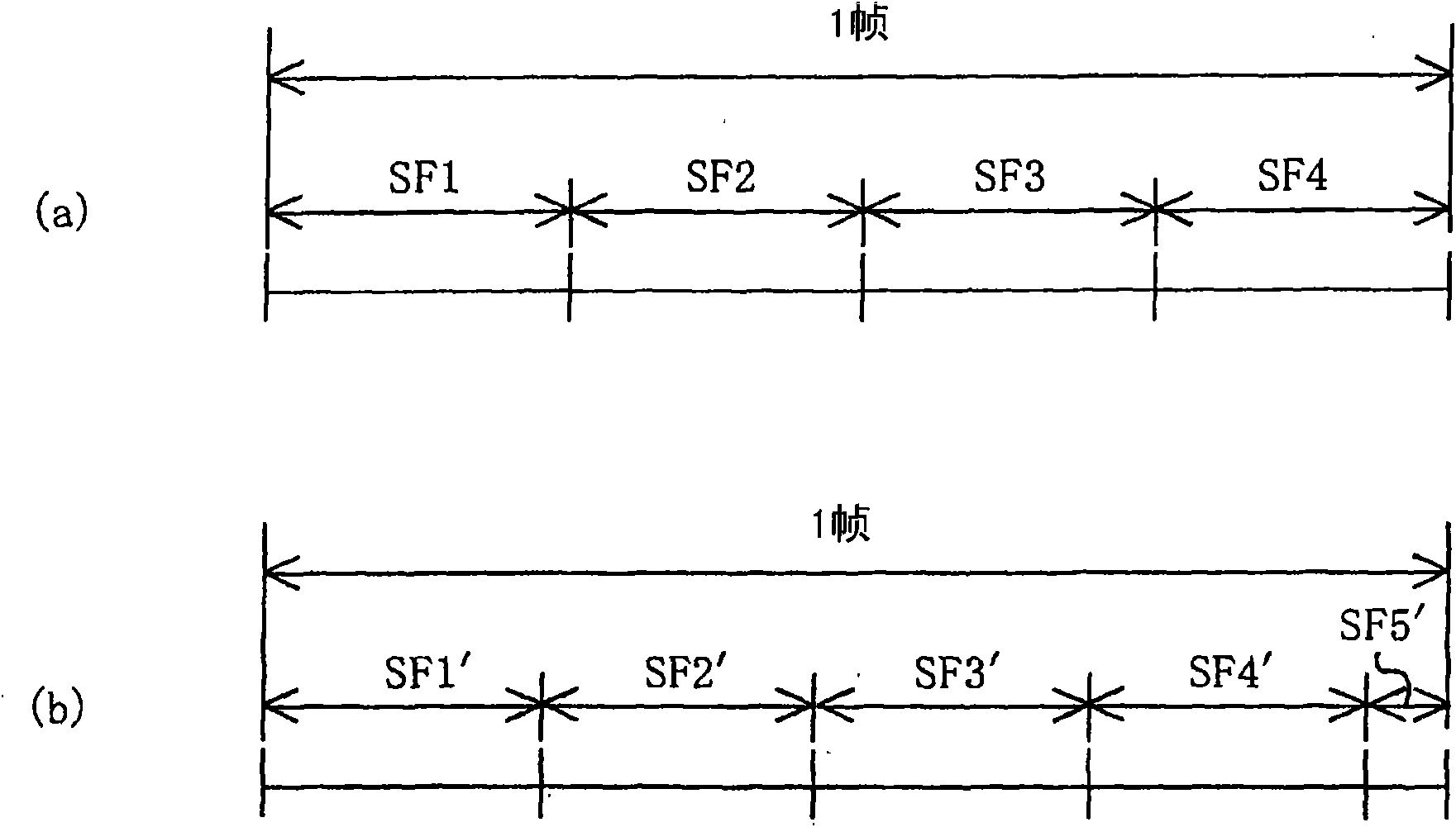
[0042] figure 1 It is a diagram for explaining the basic concept of the subframe division method in the gradation control method of the first embodiment to one output (one pin) of the driver IC.

[0043] figure 1 (a) shows an existing subframe division example, figure 1 (b) shows an example of subframe division in the present invention.

[0044] In prior art, for example, as figure 1 As shown in (a), one frame is divided into four 12-bit subframes (SF1 to SF4), but in this embodiment, as figure 1 As shown in (b), one frame is divided into four 10-bit subframes (SF1' to SF4'), and a fifth frame of 2 bits is provided to have compatibility with one frame of 12 bits.

[0045] Furthermore, the bits of these subframes create data of "1" or "0" according to the desired grayscale of each pixel.

[0046] In the prior art, for example, four 12-bit subframes are used to control the gray level of one frame. In this regard, in this embodiment, the first to fourth 10-bit subframe...

Embodiment approach 2

[0069] The first embodiment described above describes the basic concept of the subframe division method of frame data corresponding to one output (one pin) of the driver IC (that is, corresponding to one pixel).

[0070] This embodiment describes an example of a specific gradation control method for a display device in which a plurality of pixels (display elements) are arranged in a matrix to form a display screen.

[0071] Note that the concept of gradation control for one pixel is basically the same as that of the gradation control method in Embodiment 1 described above.

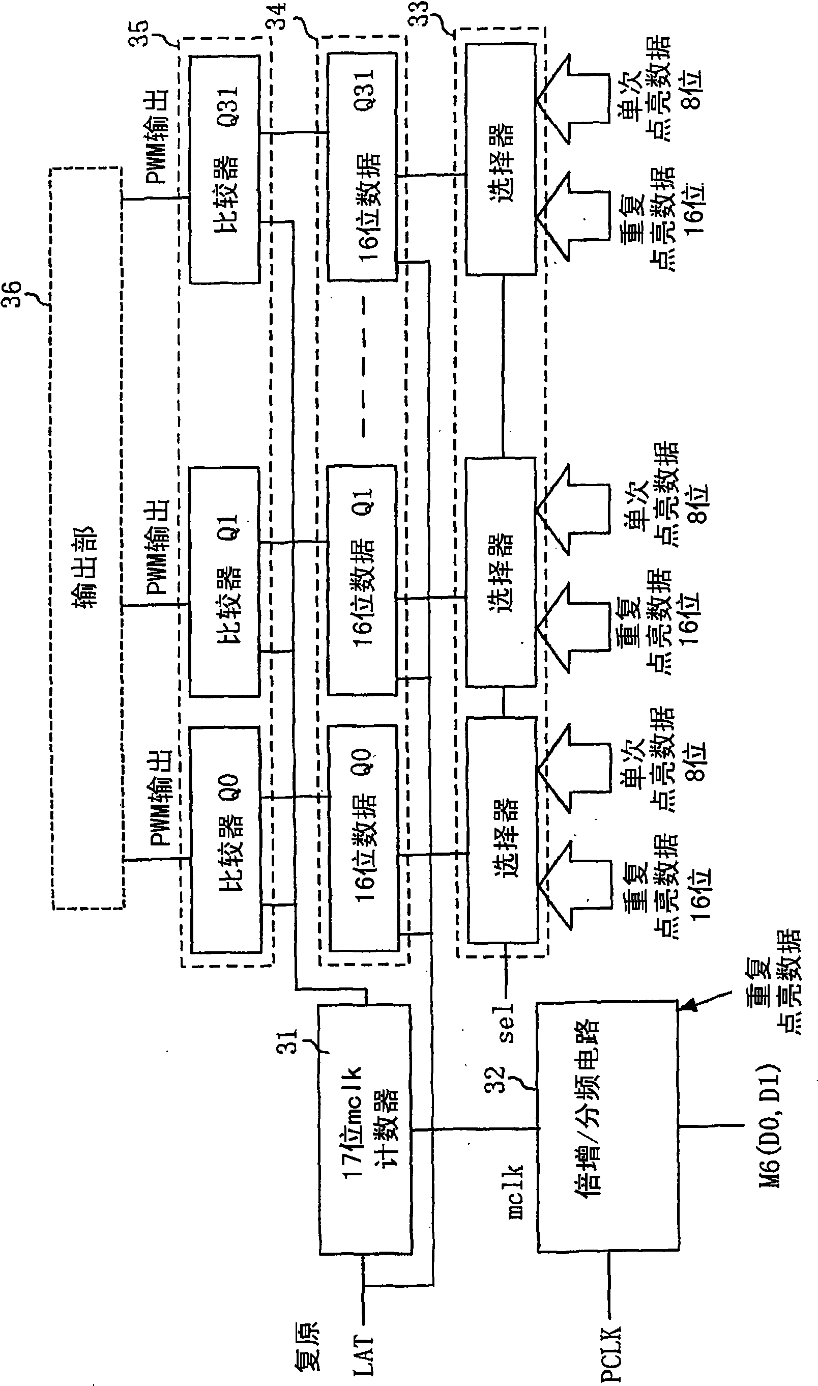
[0072] image 3 It is a diagram showing a configuration example of a PWM circuit for generating a grayscale clock (PWM clock) in the second embodiment for explaining the grayscale control method of the second embodiment.

[0073] image 3 Among them, 31 is a 17-bit mclk counter, 32 is a multiplying / dividing circuit, 33 is a selector part, 34 is a latch circuit for latching 16-bit data Q using a latch sig...


PUM


Abstract

The present invention relates to a gradation control method, for a display device, in which one frame is divided into a plurality of subframes (SF1' to SF5') and lighting times for pixels corresponding to the subframes are controlled based on the sum of respective light-emitting times in the subframes, so that gradations of the pixels are rendered; the frame is divided into n subframes (n = positive integer) (e.g., SF1' to SF4') in each of which m-bit data (m = positive integer) is set and a subframe (SF5') in which p-bit data (p = positive integer smaller than m) is set. As a result, increasein a data setting time can be suppressed, even if the number of subframes is increased in order to enable complicated gradation control.

Description

technical field [0001] The present invention relates to a display device in which display elements such as LED light-emitting elements or EL (electro-luminescence: electroluminescence) elements are arranged in a matrix, and particularly relates to a gradation control method using PWM (Pulse Width Modulation) The light emitting time of the display element which is a pixel is controlled to control the gradation. Background technique [0002] In the time-division driving method of controlling gradation by controlling the light-emitting time of pixels, one frame is divided into a plurality of subframes to display gradation. [0003] This time-division driving method divides the pixels into light-emitting time and non-light-emitting time according to digital data signals during each sub-frame, so as to express the gray scale of each pixel within one frame period. [0004] Figure 12 It is related to, for example, Japanese Special Publication No. 2005-316382 (Patent Document 1) ...

Claims


Application Information

Patent Timeline
Patent Type & Authority Applications(China)
IPC IPC(8): G09G3/30G09G3/20G09G3/32G09G3/3275
CPCG09G3/32G09G2360/16G09G3/2014G09G3/2033G09G3/2037G09G3/204G09G3/2022G09G2310/0275G09G2320/0271
Inventor 大塚尚司冈元崇前岛一也
Owner MITSUBISHI ELECTRIC CORP
Learn More