Lapel-type bag shaper with multiple conical surfaces

A bag forming and multi-cone technology, which is applied in the direction of containers, paper/cardboard containers, container manufacturing machinery, etc., can solve the problems of complex structure of bag making machine, limited selection of bag making materials, increase of manufacturing cost of bag making machine, etc.

Inactive Publication Date: 2010-03-10
JIANGNAN UNIV
View PDF0 Cites 0 Cited by
  • Summary
  • Abstract
  • Description
  • Claims
  • Application Information

AI Technical Summary

Problems solved by technology

The shoulder curved surface 3' of the existing lapel bag-making former is made of a single conical surface, and the bag-making material forms a longitudinal seam 4' after passing through the lapel bag-making former, and the longitudinal seam is formed by the inner layer and the outer layer of the bag-making material. overlapping layers (e.g. Figure 2A ), since the inner layer and the outer layer of the bag-making material are heat-sealed during the bag-making process, only the same bag-making material as the inner layer and the outer layer material can be selected, so that the selection of bag-making materials is limited and cannot be used Composite materials with different inner layer and outer layer materials are used to make bags; if it is necessary to make the bag-making materials form the inner layer Figure 2B ) of the longitudinal seam, it is necessary to add an additional transition section, so that the inner layer can be connected to the inner layer after the bag-making material is folded through the transition section. The overall height of the machine reduces the bag making efficiency and increases the manufacturing cost of the bag making machine accordingly

Method used


Image

  • Lapel-type bag shaper with multiple conical surfaces
  • Lapel-type bag shaper with multiple conical surfaces
  • Lapel-type bag shaper with multiple conical surfaces

Examples


Embodiment Construction

[0031] The specific implementation manners of the present invention will be further described in detail below in conjunction with the accompanying drawings.

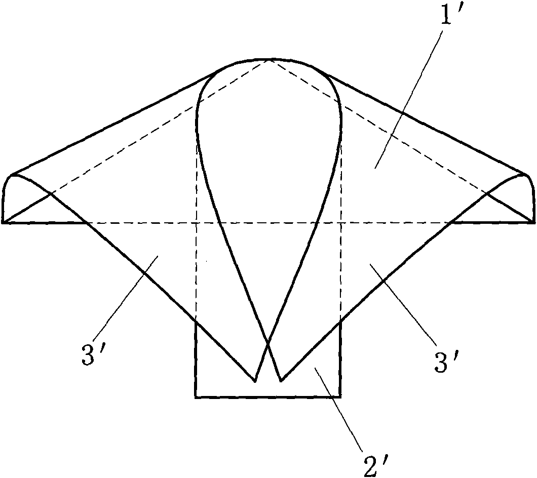
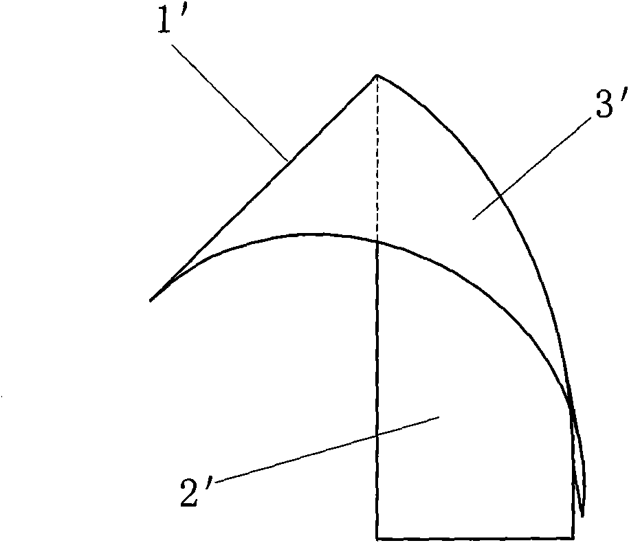
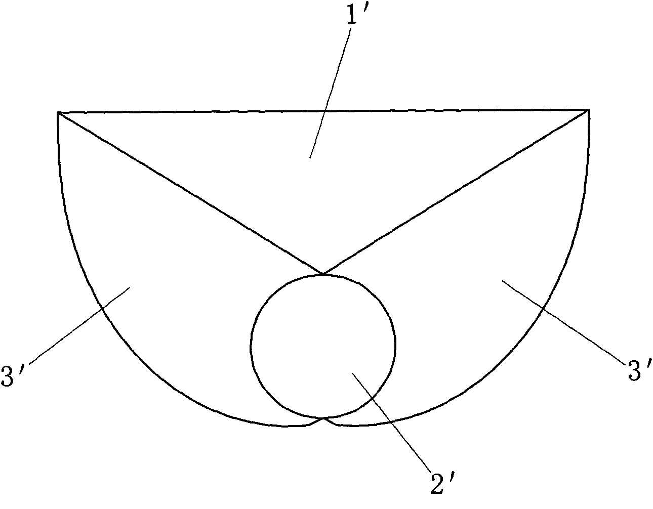
[0032] like image 3 , 4 , 5 and 6, the present invention comprises a back plane 1, a cylindrical standpipe 2 and two shoulder curved surfaces symmetrically arranged on both sides of the back plane (such as image 3 In XOZ plane symmetry), the shoulder surface is formed by connecting the first conical surface 3 and the second conic surface 4, the first conical surface 3 and the second conical surface 4 are tangent at the common generatrix 5, the first conic surface 3, There is a smooth transition between the second conical surface 4 and the back plane 1, and the back plane 1, the first conical surface 3, the second conical surface 4, and the inner wall of the cylindrical standpipe 2 together form a developable curved surface (expansion diagram as shown in FIG. Figure 7 ), two symmetrically arranged second conical surf...


PUM


Abstract

The invention relates to a lapel-type bag shaper with multiple conical surfaces, which is used for a bag shaping machine. The lapel-type bag shaper comprises a flat back surface, a cylindrical vertical pipe and curved shoulder surfaces and is characterized in that the curved shoulder surfaces consist of first conical curved surfaces and second conical curved surfaces and are tangential at a sharedbus, and the two second conical curved surfaces form opposite vertical lapels. Each of the symmetrically-arranged curved shoulder surfaces consists of two curved surfaces which can form the oppositevertical lapels. The bag shaping material passes by the lapel-type bag shaper and forms the vertical line whose inner layers are spliced so that the bag shaping material can not be restricted any more; the bag can be shaped with composite inner layer material and composite outer layer material which are different; the structures of two curved surfaces of each of the symmetrically-arranged curved shoulder surfaces can lower the overall height of the lapel-type bag shaper so as to turn over and shape the piece of flat bag shaping material; in addition, a transition section can be omitted so thatthe overall height of the bag shaper is lowered, the manufacturing cost is reduced and the bag shaping efficiency is improved.

Description

technical field [0001] The invention relates to a packaging mechanical device, in particular to a multi-cone lapel bag forming device of a bag forming machine. Background technique [0002] The lapel bag forming machine is a key part of the bag forming machine, such as Figure 1A , 1B , 1C, the lapel bag forming device includes a back plane 1', a standpipe 2' and two shoulder curved surfaces 3' symmetrically arranged on both sides of the back plane 1'. During the bag making process, the flat bag making material After passing through the back plane 1' of the lapel bag forming machine and turning over along the shoulder surface 3', it descends along the inner wall of the standpipe 2' and forms a cylindrical shape. Therefore, when the bag making material runs on the surface of the lapel bag making machine, its longitudinal and transverse Neither elongation nor shortening can occur. The shoulder curved surface 3' of the existing lapel bag-making former is made of a single coni...

Claims


Application Information

Patent Timeline
IPC IPC(8): B31B1/26
Inventor 周一届
Owner JIANGNAN UNIV
Why Eureka
Try Eureka