Fault location method based on travelling wave

A technology of traveling wave fault and location method, which is applied in the field of power system to achieve the effect of realizing fault location and overcoming high-resistance faults

Active Publication Date: 2010-03-10
BEIJING SIFANG JIBAO AUTOMATION +2
View PDF0 Cites 28 Cited by
  • Summary
  • Abstract
  • Description
  • Claims
  • Application Information

AI Technical Summary

Problems solved by technology

[0004] ●High resistance fault

Method used


Image

  • Fault location method based on travelling wave
  • Fault location method based on travelling wave
  • Fault location method based on travelling wave

Examples


Embodiment Construction

[0017] The technical solution of the present invention will be described in further detail below according to the accompanying drawings.

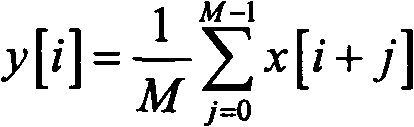
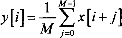
[0018] The present invention relates to the problem of traveling wave positioning of a distance measuring device in a power system. More precisely, it uses average sliding filtering and B spline wavelet transform to realize a line distance measuring algorithm according to the sampling value of the distance measuring device.

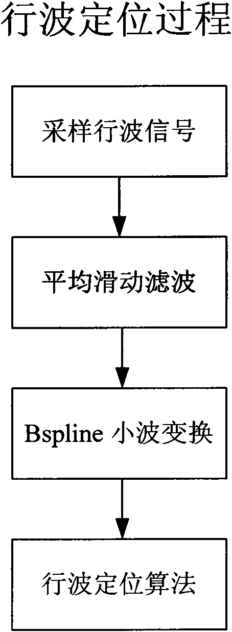
[0019] as attached figure 1 Shown is a logical schematic diagram of the traveling wave positioning method of the present invention. The present invention is a fault location method based on traveling waves, and the discrimination method is based on the following signal processing algorithm; the method includes the following steps:

[0020] (1) The line ranging device samples the current waveform of the line transformer to obtain the instantaneous value of the current, and the sampling rate is 1MHz;

[0021] (2) Prepr...


PUM


Abstract

The invention discloses a fault location method based on a travelling wave when the signal / noise ratio is at a lower level. Because of the strengthening of capacitance effects of a high-voltage powertransmission line, the travelling wave decays comparatively large when is transmitted along the line, in particular when high resistance fault or low voltage inception angle ground fault occurs, the initial energy of the travelling wave is very low, and the energy is comparatively low after line capacitance decaying, and is mainly overwhelmed by noise. Therefore, as far as the present used travelling wave method is concerned, if a sampled signal is not preprocessed, wavelets transformation is directly used for carrying out fault location, but correct result can't be obtained. In the fault location method, a moving average filter is firstly used to preprocess the sampled signal, and then Bspline wavelet transformation is used to realize fault location. Because the moving average filter can effectively restrain the noise without decaying an abrupt signal, based on this, fault location at a low signal / noise ratio can be realized by utilizing the Bspline wavelet transformation.

Description

technical field [0001] The invention belongs to the field of power systems, and in particular relates to a distance measuring device of a power system that can accurately realize a fault location method based on traveling waves when the signal-to-noise ratio is low. Background technique [0002] With the expansion of the scale of my country's power grid and the construction of various large-scale power projects, 500kV lines have been widely used. The power network has gradually become the main network with 500kV transmission lines. At present, lines above 220kV are equipped with traveling wave ranging devices as standard to shorten the time of line hunting and find fault locations in time. However, as far as the operating wave ranging device is put into operation at present, the ranging error often occurs, and sometimes it is even impossible to effectively identify the traveling wave signal. The main reasons are: [0003] ●Line capacitance attenuation [0004] ●High resi...

Claims


Application Information

Patent Timeline
Patent Type & Authority Applications(China)
IPC IPC(8): G01R31/08
Inventor 任磊徐振宇杜兆强田文辉
Owner BEIJING SIFANG JIBAO AUTOMATION
Why Eureka
Try Eureka