
Display module and assembling method thereof

A technology for displaying modules and assembly methods, applied to static indicators, nonlinear optics, instruments, etc., which can solve problems such as difficult to remove, difficult to rework polarizers, bright or dark spots, etc.

Inactive Publication Date: 2010-03-10
AU OPTRONICS (SUZHOU) CORP LTD +1
View PDF0 Cites 6 Cited by
  • Summary
  • Abstract
  • Description
  • Claims
  • Application Information

AI Technical Summary

Problems solved by technology

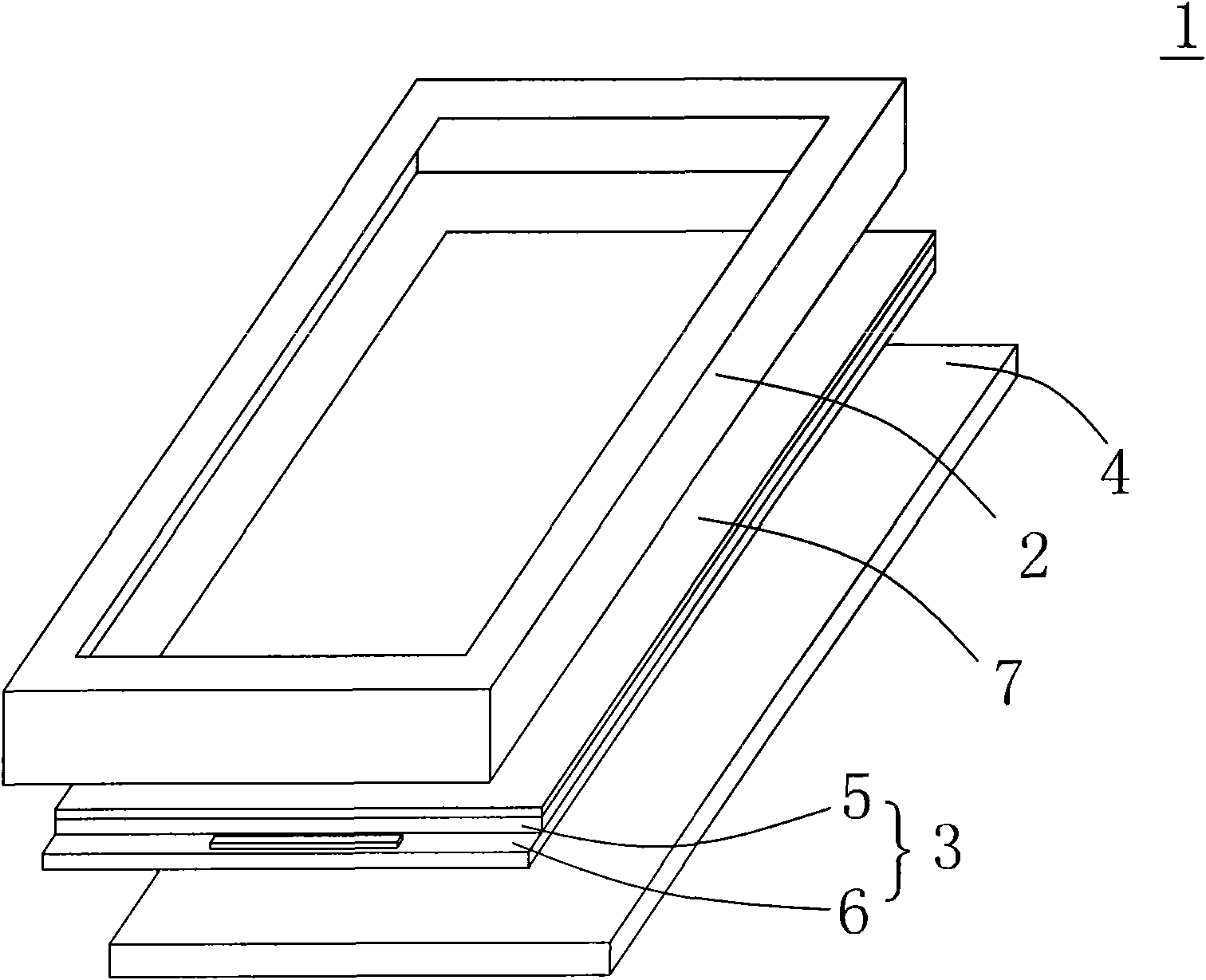
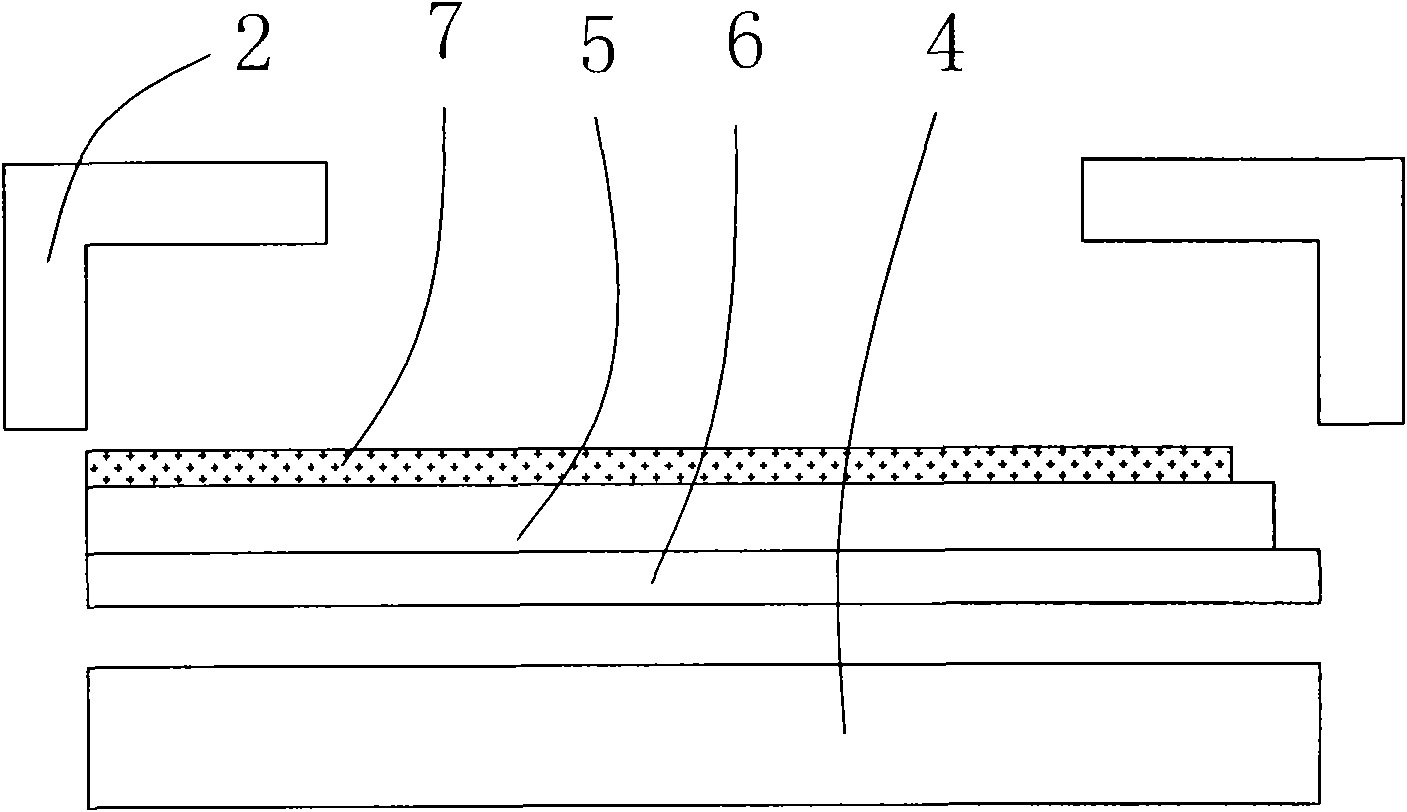
[0005] 3. If foreign matter enters between the polarizer 7 and the CF substrate 5 when the polarizer 7 is attached, it will be difficult to remove, resulting in defects such as bright spots or dark spots; and
[0006] 4. It is not easy to rework after the polarizer 7 is attached, and it will easily produce fragments

Method used


Image

  • Display module and assembling method thereof
  • Display module and assembling method thereof
  • Display module and assembling method thereof

Examples


Embodiment Construction

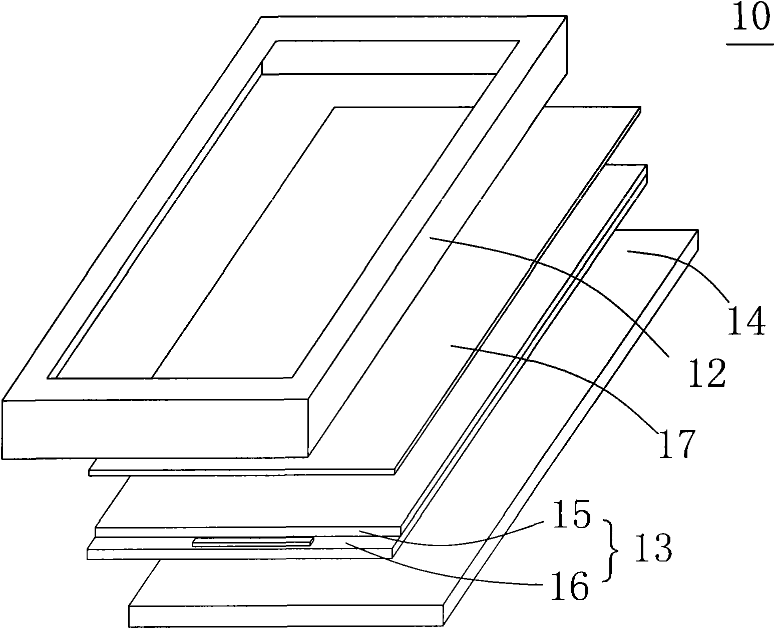
[0028] See Figure 2A and Figure 2B , Figure 2A Shown is a schematic diagram of a first embodiment of a display device according to the present invention, Figure 2B shown as Figure 2A A schematic cross-sectional view of the display device in . The display module 10 provided by the present invention includes a display panel 13 , a front frame 12 and a first polarizer 17 . The display module 10 is, for example, a liquid crystal display module, and the corresponding display panel 13 is a liquid crystal display panel. The liquid crystal display panel 13 includes a first substrate 15 and a second substrate 16 opposite to each other. In this embodiment, the first substrate 15 is a color filter substrate as an example, and the second substrate 16 is a thin film transistor array substrate.

[0029] The front frame 12 is disposed on a side of the first substrate 15 opposite to the second substrate 16 , and the front frame 12 has a first surface 21 and a second surface 22 oppos...


PUM


Abstract

The invention provides a display module and an assembling method thereof. The display module comprises a display panel, a front frame and a first polarizer film, wherein the display panel comprises afirst base plate and a second base plate which are arranged oppositely; the front frame is arranged at one side of the first base plate corresponding to the second base plate and is provided with a first surface and a second surface which are arranged oppositely, and the second surface of the front frame faces the display panel; and the first polarizer film is fixedly arranged on the front frame and is provided with a third surface and a fourth surface which are arranged oppositely, and the third surface faces the display panel.

Description

technical field [0001] The present invention relates to a display module, in particular to a display module with a polarizer arranged on a front frame and an assembly method thereof. Background technique [0002] See Figure 1A and Figure 1B , Figure 1A Shown is a schematic diagram of a liquid crystal display device in the prior art, Figure 1B shown as Figure 1A A schematic cross-sectional view of a liquid crystal display device in . In the prior art, a liquid crystal display device 1 includes a front frame 2, a liquid crystal display panel 3 and a backlight module 4, the backlight module 4 provides a light source for the liquid crystal display panel 3, and the front frame 2 is used to fix the liquid crystal display panel 3 and the backlight module 4. The liquid crystal display panel 3 includes a color filter (CF) substrate 5 and a thin film transistor array (TFT) substrate 6 that are oppositely arranged, wherein the upper and lower surfaces of the liquid crystal displ...

Claims


Application Information

Patent Timeline
Patent Type & Authority Applications(China)
IPC IPC(8): G02F1/13G02F1/133G02F1/1335G02F1/1362G02F1/1368
Inventor 黄凤兴杨娟
Owner AU OPTRONICS (SUZHOU) CORP LTD
Learn More