Simulation method of shield tunnel joint structure

A simulation method and technology of shield tunneling, applied in the field of simulation of shield tunnel joint structure, can solve problems such as large errors in lining structure, unreasonable description of joint deformation characteristics, difficulty in determining joint simulation parameters, etc., and achieve reasonable calculation results , the effect of a reasonable reflection

Inactive Publication Date: 2010-03-10
TONGJI UNIV
View PDF0 Cites 26 Cited by
  • Summary
  • Abstract
  • Description
  • Claims
  • Application Information

AI Technical Summary

Problems solved by technology

[0011] The existing calculation methods mainly have the following two problems: 1. The above calculation methods are mainly developed for the longitudinal force and longitudinal settlement of the tunnel, so they cannot reasonably describe the deformation cha

Method used


Image

  • Simulation method of shield tunnel joint structure
  • Simulation method of shield tunnel joint structure
  • Simulation method of shield tunnel joint structure

Examples


Embodiment Construction

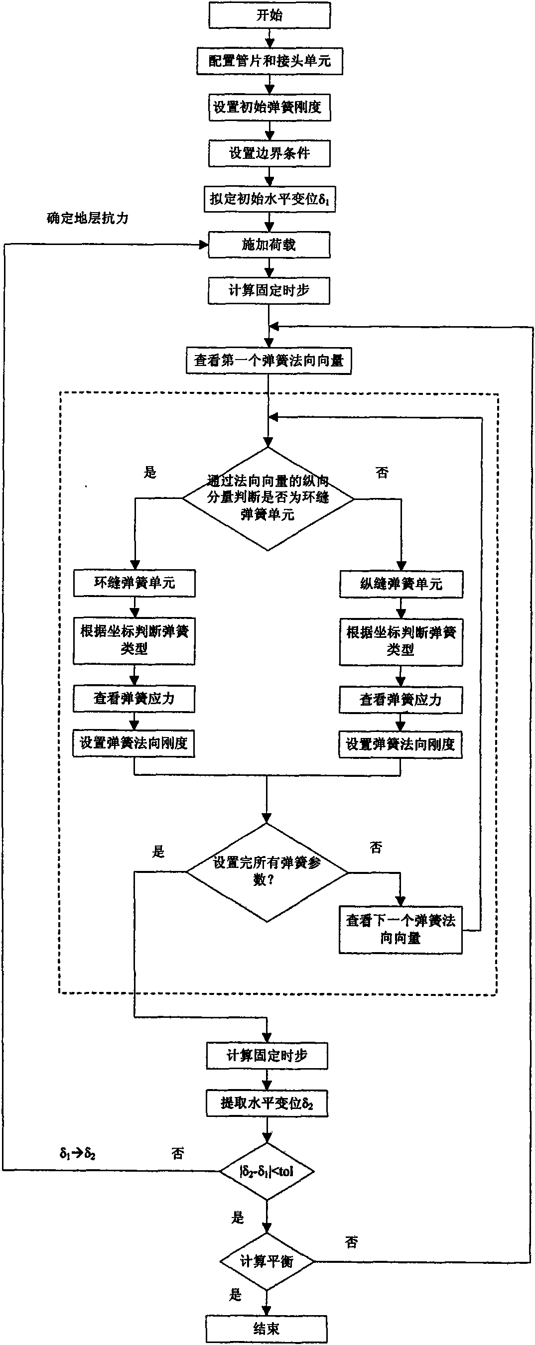
[0043] see figure 1 , the implementation steps are as follows:

[0044] (1) start;

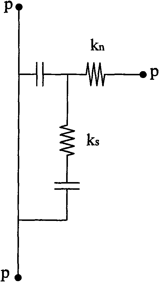
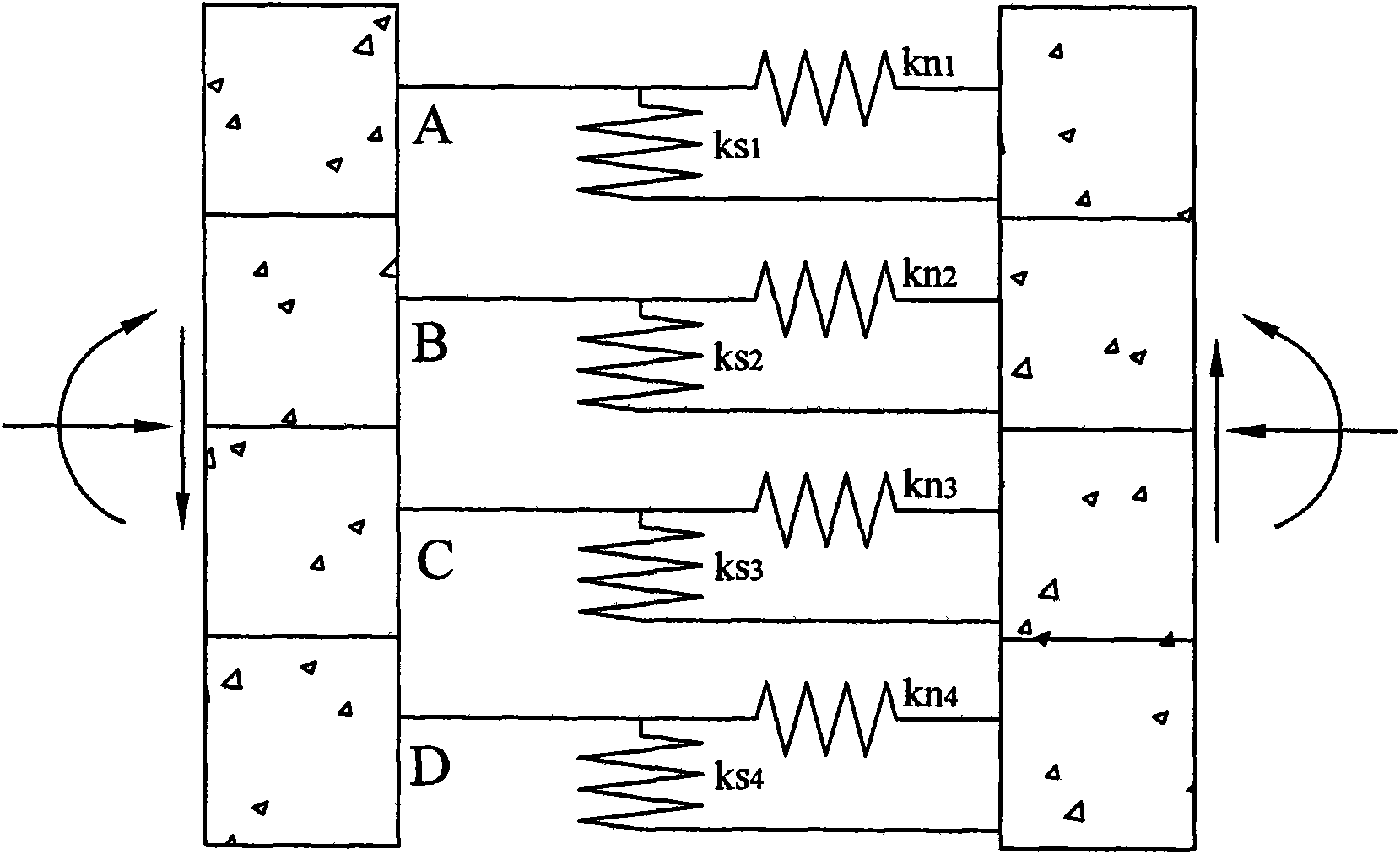
[0045] (2) Set up the joint unit, using four sets of springs to simulate the four-layer structure of the segment. From the inside to the outside, the first layer of springs simulates the inner force transmission liner D, the second layer of springs simulates bolts C, and the third layer of springs simulates the outer force transmission liner Pad B, the fourth layer of springs simulates elastic gasket A, each group of springs includes multiple sub-springs, the number of sub-springs in the circumferential direction can be determined according to the size of the segment and the calculation accuracy, and the number in the axial direction is also determined by the calculation accuracy;

[0046] (3) Set the initial spring stiffness, including normal stiffness and shear stiffness, set the boundary conditions according to the actual conditions, and draw up the initial displacement of the joint δ 1 ;...


PUM


Abstract

The invention discloses a simulation method of a shield tunnel joint structure, which is characterized by comprising the steps of: (1) setting joint units: dispersing joint contact surfaces into a plurality of nodes, wherein the nodes are mutually connected by the joint units of simulation springs, circumferential upper joint units have a plurality of layers to respectively simulate force transmission liners, bolts and gaskets in real joints, and the types of the joint units at the same layer are the same; (2) setting the rigidity, the boundary condition and the joint initial displacement Delta1 of initial springs; (3) applying load; (4) examining a first joint unit; (5) setting the normal rigidity of the spring according to the type of the joint unit; (6) judging whether all the joint units are set, if so, starting the next step (7), and if not, examining the next joint unit and retuning to the step (5); (7) counting the real displacement delta 2 of the joints; and (8) comparing the delta1 with the delta2, if the difference between the two is in the allowed range tol, completing the account, and counting the deformation of the joints in the tunnel, and if the difference between the two is over the allowed range, counting the imposed load of the tunnel according to the delta2, and returning back to the step (3) to reapply the load. Based on the structure characteristics of theliner structure joints, the method builds the mechanical model of the liner structure joints, dynamically adjusts spring parameters in the process of counting according to the obtained node spring stress or the normal displacement, and uses joint models to count the whole ring liner structure. The method can consider the performance of the circumferential joints and the longitudinal joints of theliners, count the inner force and the deformation of the duct pieces and the joints of the liners, and more exactly show the status of deformation and force of the duct pieces.

Description

technical field [0001] The invention relates to the field of calculation of tunnel structure models, in particular to a method for simulating the joint structure of a shield tunnel. Background technique [0002] The shield tunnel is assembled from segments. During the long-term operation of the tunnel, due to the influence of various external factors, the tunnel will undergo uneven settlement along the longitudinal direction. Water seepage and mud leakage. At present, water seepage in tunnels is one of the main problems in operating tunnels. Therefore, how to reasonably simulate joint deformation caused by tunnel longitudinal uneven settlement is very important to study the performance of operational tunnels. Whether the joint simulation is reasonable or not determines the rationality and accuracy of joint deformation calculation. At present, there are mainly the following methods for the simulation of tunnel longitudinal deformation: [0003] (1) Longitudinal beam-spring ...

Claims


Application Information

Patent Timeline
IPC IPC(8): G06F17/50
Inventor 张冬梅黄宏伟樊振宇
Owner TONGJI UNIV
Why Eureka
Try Eureka