Method and device for tail biting decoding

A decoding device and decoding technology, applied in the field of encoding and decoding, can solve the problems of large decoding delay and low accuracy of backtracking state, and achieve the effect of improving accuracy and reducing decoding delay

Inactive Publication Date: 2010-03-10
HUAWEI TECH CO LTD
View PDF0 Cites 15 Cited by
  • Summary
  • Abstract
  • Description
  • Claims
  • Application Information

AI Technical Summary

Problems solved by technology

[0020] Decoding is performed by connecting three transmission blocks in series, and the backtracking state is determined according to the acc

Method used


Image

  • Method and device for tail biting decoding
  • Method and device for tail biting decoding
  • Method and device for tail biting decoding

Examples


Embodiment Construction

[0041] The following will clearly and completely describe the technical solutions in the embodiments of the present invention with reference to the accompanying drawings in the embodiments of the present invention. Obviously, the described embodiments are only some, not all, embodiments of the present invention. Based on the embodiments of the present invention, all other embodiments obtained by persons of ordinary skill in the art without creative efforts fall within the protection scope of the present invention.

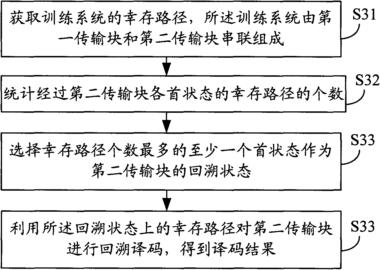
[0042] image 3 A schematic diagram of a tail-biting decoding method provided by an embodiment of the present invention, the method may include:

[0043]S31: Obtain a surviving path of a training system, where the training system is composed of a first transmission block and a second transmission block connected in series;

[0044] S32: Count the number of surviving paths passing through each first state of the second transmission block;

[0045] S33: Select at l...


PUM


Abstract

The embodiment of the invention provides a method and a device for tail biting decoding, aiming at improving the accuracy of determining backtracking state and reducing the decoding delay. The method provided by the embodiment of the invention comprises the following steps: acquiring a survivor path of a training system formed by the series connection of a first transmission block and a second transmission block; counting the number of survivor paths passing through each first state of the second transmission block; selecting at least one initial state with maximum survivor paths as the backtrack state of the second transmission block; and obtaining a decoding result by utilizing the survivor paths on the backtracking state to perform backtrack decoding of the second transmission block.

Description

technical field [0001] The present invention relates to the technical field of coding and decoding, in particular to a tail biting decoding method and device. Background technique [0002] In the prior art, the encoding and modulation method of the tail-biting convolutional code is proposed, and the tail-biting convolutional code used in the LTE (Long Term Evolution, Long Term Evolution) system is used as an example for illustration. The (3, 1, 6) encoder is as follows: figure 1 shown. The encoder has a constraint length of 7 and a code rate of 1 / 3. figure 1 generator polynomial G i The binary sequence of (i=0, 1, 2) represents the input data and the connection status of the 6 shift registers and the i-th output of the encoder. Binary 0 means not connected, binary 1 means connected. figure 1 The middle adder is performed in the GF(2) field. The initial state of the shift register is the last 6 bits of the input bit sequence, so that η 0 , η 1 , η 2 ,...,η 5 The six ...

Claims


Application Information

Patent Timeline
IPC IPC(8): H03M13/35H03M13/23
CPCH03M13/413
Inventor 曾云宝魏璟鑫
Owner HUAWEI TECH CO LTD
Why Eureka
Try Eureka