
Chamfering device and chamfering method for metallic material

A technology of metal materials and chamfering devices, which can be used in metal processing equipment, accessories of tool holders, turning equipment, etc., and can solve problems such as poor working environment

Inactive Publication Date: 2010-03-10
NIPPON STEEL CORP
View PDF4 Cites 1 Cited by
  • Summary
  • Abstract
  • Description
  • Claims
  • Application Information

AI Technical Summary

Problems solved by technology

The production of cutting dust, etc. causes a bad working environment

Method used


Image

  • Chamfering device and chamfering method for metallic material
  • Chamfering device and chamfering method for metallic material
  • Chamfering device and chamfering method for metallic material

Examples


Embodiment

[0061] Hereinafter, the present invention will be described in more detail using examples.

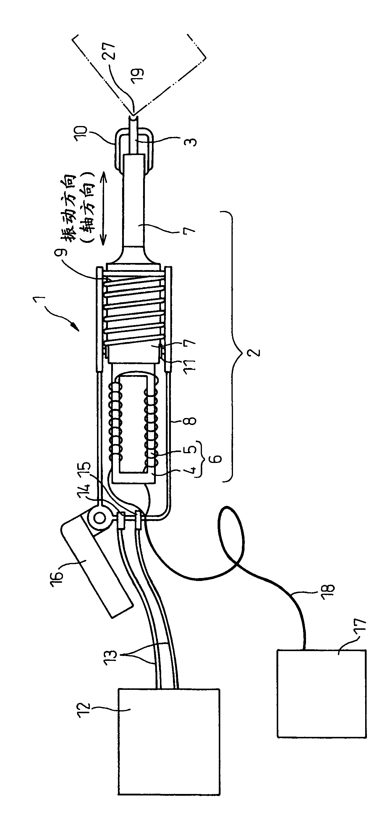
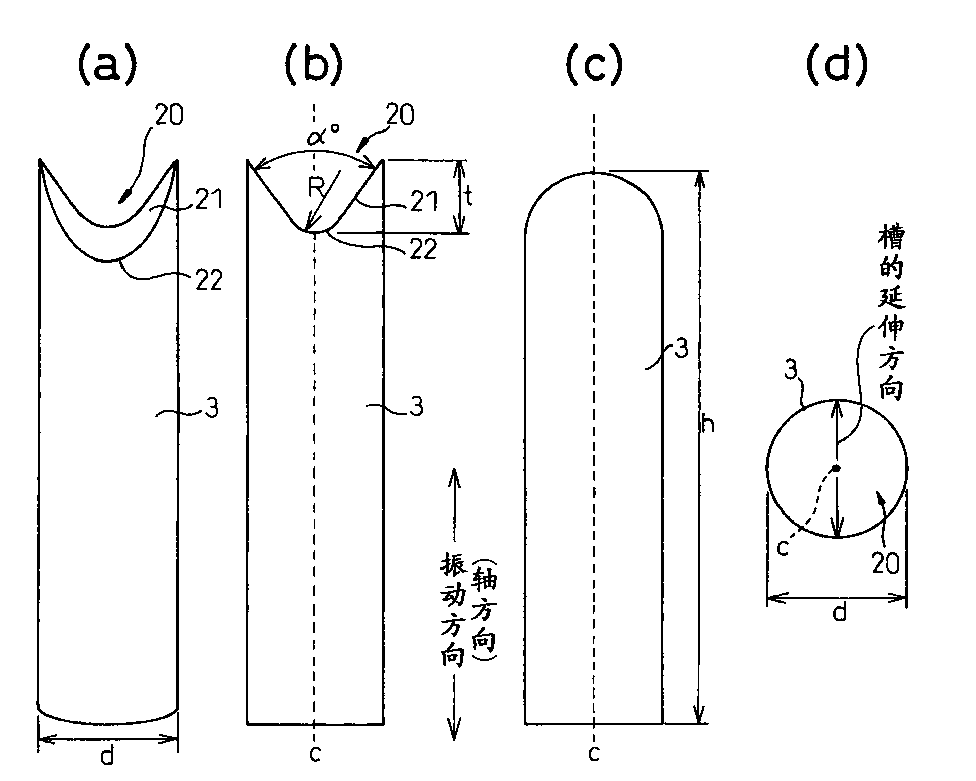
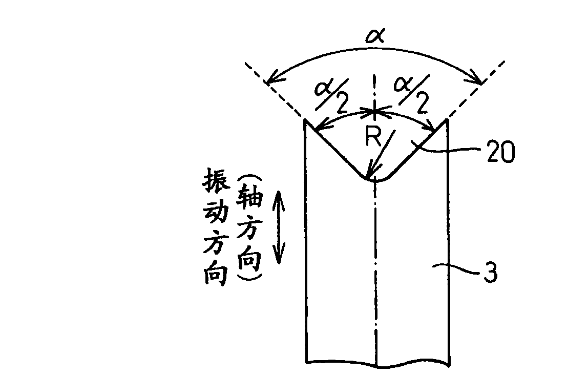
[0062] use figure 1 The shown chamfering device chamfers three corners of five steel parts samples 1 to 5 with a cross-section of about a square (corner angle of about 90°) and strength grades ranging from 400 to 600 MPa. The chamfering pin is made of HRC62 SKH material, a cylindrical rod with a diameter of 4.8mm and a length of 35mm. The opening angle of the groove at the top is 90°, and the radius of curvature of the bottom of the groove is Figure 7 As shown in (a) to (c), it changes from 1R to 3R. respectively with different radii of curvature at the bottom of the groove, as described above Figure 7 The chamfering pins shown in (a) to (c) chamfer the three corners of the above-mentioned steel member sample. For comparison, one corner was left as an unprocessed part while maintaining the corner condition before chamfering. The conditions of chamfering treatment (the radius of c...


PUM


Abstract

Provided is a chamfering device capable of executing the corner portion of a metallic material or a metallic structure member under economical, efficient and satisfactory working environments. The chamfering device for the metallic material comprises a chamfering oscillation terminal extending at the leading end portion of the oscillating direction of an oscillating device and in the direction perpendicular to the oscillating direction and including a bottom portion having a section of a radius of curvature (R) normal to that extending direction and a groove opened toward leading end side, andthat oscillating device for vibrating the oscillation terminal in the axial direction thereof in a frequency of 10 Hz to 50 KHz and in a power of 0.1 to 4 KW.

Description

technical field [0001] The invention relates to a chamfering device and a chamfering method of corners of metal materials and metal structural parts, and relates to a chamfering device and method using beating vibration. Background technique [0002] Metal materials such as steel plates and steel parts used as bridges, steel frames, and shipbuilding frames, and metal structural parts are often coated with various coatings before or after assembly as necessary. For example, at the time of assembling a ship hull, steel parts are at least coated for rust prevention. [0003] On the other hand, since the edge of a steel plate or a steel member is a sharp corner, when coating is applied, the coating film tends to come off from the corner. In order to prevent the coating film from peeling off, the corners are chamfered, and the sharp corners are turned into smooth curved surfaces with curvature. Known methods for this chamfering include: grinding with a grinder, cutting with a c...

Claims


Application Information

Patent Timeline
IPC IPC(8): B21D19/00B23D79/00B21D22/02
CPCB23D79/00B23B2220/04B21D19/08B23B29/125B23C2220/20B21D19/00B21D22/02
Inventor 野濑哲郎岛贯广志
Owner NIPPON STEEL CORP
Learn More