Cleaning unit of liquid material discharge device, and roller rotation control method implemented in cleaning unit

A technology for cleaning devices and liquid materials, which is applied to the device for coating liquid on the surface, printing, coating, etc., which can solve the problems of reduced ejection performance, poor cleaning reliability, and difficulty in cleaning, and achieve stable ejection performance, The effect of high reliability

Inactive Publication Date: 2010-03-10
SHARP KK
View PDF4 Cites 2 Cited by
  • Summary
  • Abstract
  • Description
  • Claims
  • Application Information

AI Technical Summary

Problems solved by technology

Since the shape of the discharge surface of the nozzle plate has a great influence on the discharge performance, if the discharge surface is damaged as described above, the discharge performance will be significantly reduced
[0015] In addition, even if the scraper blade of Patent Document 3 is brought into contact with the ejection surface of the nozzle plate, if the roller for cleaning the scraper blade is a sponge or a brush, it may cause damage to the scraper blade. Scraping may cause damage to the ejection surface
[0016] Moreover, when the components for cleaning the blade have a structure that absorbs the liquid material adhering to the blade like a sponge or a brush, the components need to be replaced frequently,

Method used


Image

  • Cleaning unit of liquid material discharge device, and roller rotation control method implemented in cleaning unit
  • Cleaning unit of liquid material discharge device, and roller rotation control method implemented in cleaning unit
  • Cleaning unit of liquid material discharge device, and roller rotation control method implemented in cleaning unit

Examples


Embodiment Construction

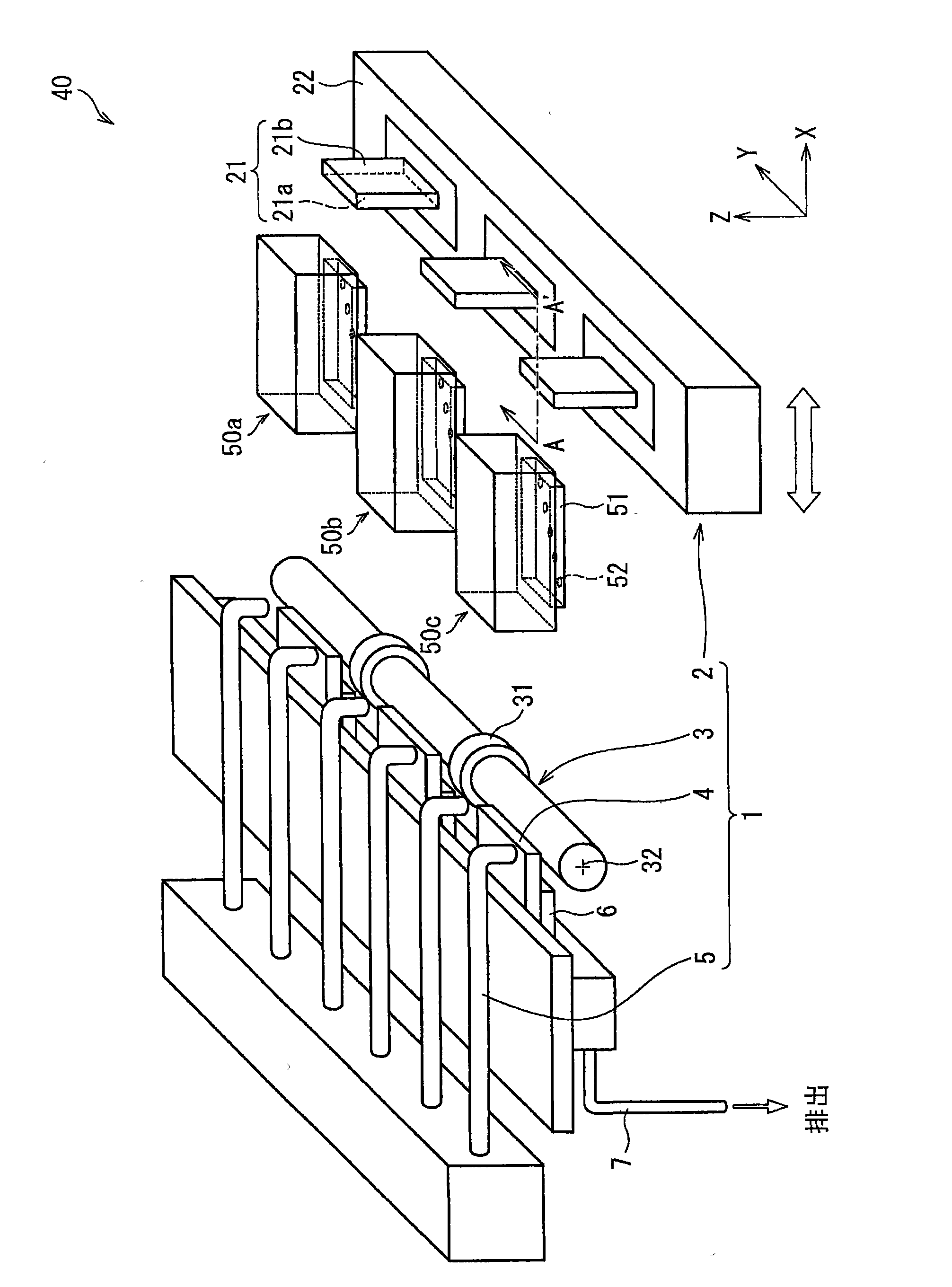
[0104] according to Figure 1 to Figure 12 One embodiment of the present invention will be described. In addition, in the following description, in order to implement the present invention, various limitations that are technically desirable are added, but the scope of the present invention is not limited to the following embodiments and drawings.

[0105] figure 1 It is a figure which shows the structure of the inkjet type liquid material discharge apparatus (hereinafter referred to as a liquid material discharge apparatus) of this embodiment. The liquid material ejection device 40 in the present embodiment can be for example red (R), blue (B), the ink of green (G) three primary colors is ejected to a material to be ejected to manufacture by R, B, G. It is used when the color filter (color filter) composed of three kinds of filters (filter) is used. Therefore, in this embodiment, a liquid material ejection device that ejects three kinds of R, B, and G inks will be describe...


PUM


Abstract

A cleaning mechanism (1) provided in a liquid material discharge device (40) comprises a blade (21) for removing ink adhering to a discharge surface, a roller (3) for removing a liquid material from the blade (21), and a motor (8) for moving the blade (21) from a position where the blade abuts on the discharge surface to a position where the blade abuts on the roller (3). The roller (3) is configured to uniformly abut on the blade (21) and the rotation thereof is controlled by a control means while the roller is abutting on the blade (21). This provides a cleaning unit with which the dischargesurface of the liquid material discharge device can be cleaned with high reliability, the discharge surface is prevented from being scratched by cleaning, and with which stable discharging efficiencycan be realized.

Description

technical field [0001] The present invention relates to a cleaning device of a liquid material ejection device and a roller rotation control method performed in the cleaning device. ) the liquid material attached to the discharge surface of the liquid material discharge device; and a cleaning unit for removing the liquid material obtained by scraping with a scraper blade from the above discharge surface, and in particular relates to a cleaning A cleaning device in which the unit is always in uniform contact with the discharge surface doctor blade when the unit is in contact with the discharge surface doctor blade, and a roller rotation control method performed in the cleaning device. Background technique [0002] A liquid material ejection device such as an inkjet type has a nozzle plate formed with a plurality of nozzles for ejecting a liquid material, and ejects a liquid material (such as ink) from the ejection surface of the nozzle plate on which an ejection port is arran...

Claims


Application Information

Patent Timeline
IPC IPC(8): G02B5/20B05C5/00B05C11/10B41J2/165
CPCB41J2/16541B41J2/16544
Inventor 牧冈广茂家根田刚士无类井格
Owner SHARP KK
Why Eureka
Try Eureka