
Print head, printer

A technology of printing head and mounting table, which is applied in printing, inking device, lighting device, etc., and can solve the problem of high cost

Inactive Publication Date: 2011-09-14
ULVAC INC
View PDF1 Cites 0 Cited by
  • Summary
  • Abstract
  • Description
  • Claims
  • Application Information

AI Technical Summary

Problems solved by technology

[0015] However, this method has problems in that high-precision microfabrication technology of a silicon plate is required to produce a columnar structure, and the manufacturing cost becomes high.

Method used


Image

  • Print head, printer
  • Print head, printer
  • Print head, printer

Examples


Embodiment Construction

[0045] figure 1 Reference numeral 50 is an example of a printing device of the present invention.

[0046] This printing apparatus 50 has a base 51 on which a substrate mounting table 53 is arranged via a mounting table moving device 52 . A device for moving the substrate mounting table 53 is provided on the mounting table moving device 52 , and the substrate mounting table 53 can reciprocate on the base 51 .

[0047] A bridge 54 is arranged at a position above the moving range of the substrate stage 53 . A head moving device 56 is provided on the bridge 54 , and the printing head 1 is movably attached to the head moving device 56 . A device for moving the print head 1 is provided on the head moving device 56 , and the print head 1 can reciprocate in a direction perpendicular to the reciprocation direction of the substrate stage 53 at a position above the substrate stage 53 .

[0048] The printing device 50 is provided with a discharge liquid tank 57 that stores the dischar...


PUM


Abstract

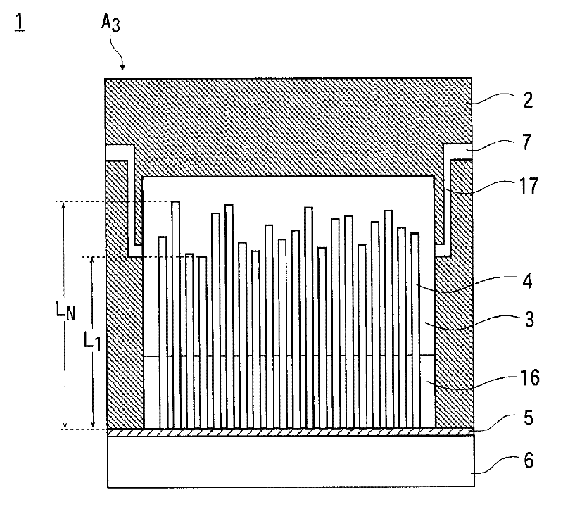
Vibration is prevented from being transmitted via a common ink chamber (8) or a fixed substrate (3). A porous member (11) is arranged between the common ink chamber (8) and a pressure generation chamber (9) so that the discharged liquid moves from the common ink chamber (8) to the pressure generation chamber (9) while passing through the interior of the porous member (11). Vibration generated in one pressure generation chamber (9) is damped through the porous member (11) when the vibration is transmitted to another pressure generation chamber (9) via the common ink chamber (8), and thereby no crosstalk is generated. Furthermore, when piezoelectric vibrators (4) having different lengths are fixed to the same fixed substrate (3) and the resonance frequencies thereof are differentiated, vibration is not transmitted to the pressure generation chamber (9) via the fixed substrate (3) and the piezoelectric vibrator (4), and thereby the crosstalk is generated further less.

Description

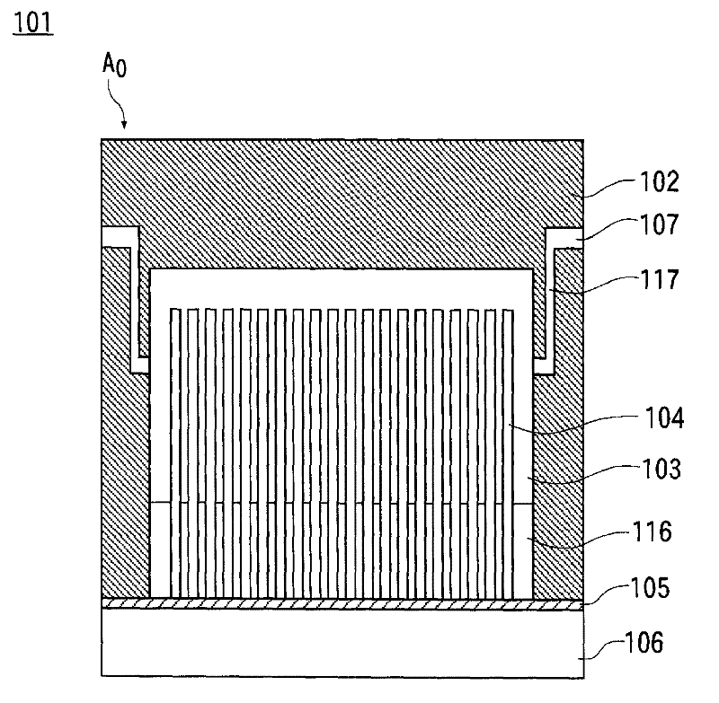
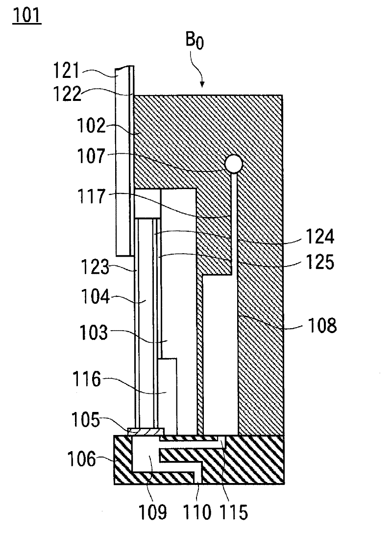
technical field [0001] The present invention relates to a printing head and a printing device that discharges a discharge liquid from a discharge hole and lands it on a discharge target such as a substrate, and particularly relates to a printing head and a printing device used in the manufacture of liquid crystal or EL display elements, etc. . Background technique [0002] In recent years, inkjet type discharge devices have been used in the production of color filters for liquid crystal display devices and organic EL display devices. [0003] The reference numeral 101 in Fig. 5(a), (b) is a part of the printing head of such an ejection device, and the reference numeral A in Fig. 5(a) 0 is a rough front view of the internal structure, and the reference sign B in Fig. 5(a) 0 It is a schematic side view. [0004] A nozzle plate 106 is provided at a position below the casing 102 of the print head 101 , and a plurality of pressure generating chambers 109 are provided in the no...

Claims


Application Information

Patent Timeline
Patent Type & Authority Applications(China)
IPC IPC(8): B05C5/00B41J2/045B41J2/055G02B5/20H01L51/50H05B33/10
CPCB41J2/055B41J2/14274B41J2002/14419B41J2002/14403B41J2202/09H01L51/0005H10K71/135B41J2/14233
Inventor 宫田贵裕村田真朗柴智志矢作充汤山纯平
Owner ULVAC INC
Learn More