Single-arm combined boring tool

A combined, boring tool technology, applied to boring bars, accessories of tool holders, tools for lathes, etc., can solve the problems of cumbersome structure, troublesome combination, inconvenient adjustment, etc. The effect of a wide range of production and processing

Inactive Publication Date: 2010-03-17
NFC (SHENYANG) METALLURGICAL MACHINERY CO LTD
View PDF0 Cites 4 Cited by
  • Summary
  • Abstract
  • Description
  • Claims
  • Application Information

AI Technical Summary

Problems solved by technology

[0002] At present, SANDVIK Cormant, the most famous tool manufacturer in the world, produces and processes large-diameter single-arm boring tools Φmax=981.6mm. 4 sets of heavy systems; (if processing to Φ1150mm, you need to add 2 sets) The fine boring unit is composed of a knife card, a fine boring head, and an extended slider, which is troublesome to combine. fine boring
[0003] The double-edged large-aperture boring tool Φmax=810mm produced by the domestic Chengdu Measuring Tool and Cutting Tool Factory has a simple structure, but the connection with the handle is slightly complicated, and the double-edged structure; virtually increases the manufacturing process and cycle, and the structure is heavy. Φ490-Φ810 need 3 sets of boring tool system (if machining Φ1150mm, 3 sets are required)
[0004] The common disadvantages of large-aperture boring tools at home and abroad are: the adjustable range is small, and they need to be purchased in groups to cover a wide range of processing, and the boring tools above Φ500 are not in stock and need to be ordered for production; foreign structures are complex, domestic structures are heavy, and manufacturing costs High, inconvenient to adjust and long lead time (45 days); at least 6 sets of tools are required from Φ550-Φ1200

Method used


Image

  • Single-arm combined boring tool
  • Single-arm combined boring tool
  • Single-arm combined boring tool

Examples


Embodiment Construction

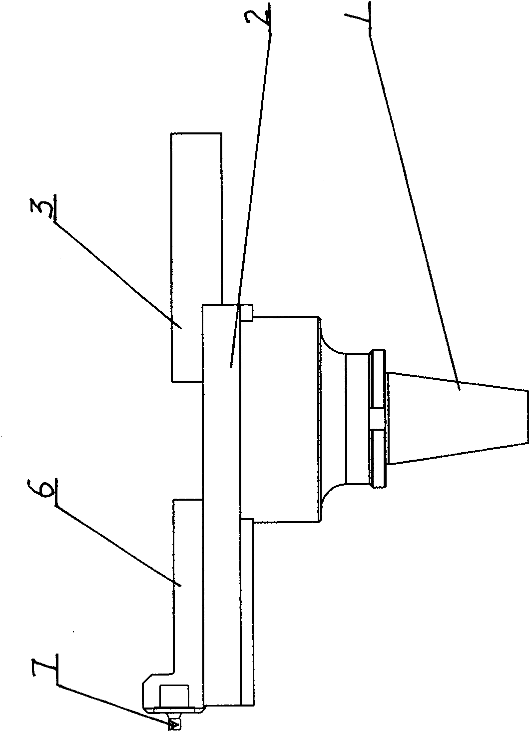
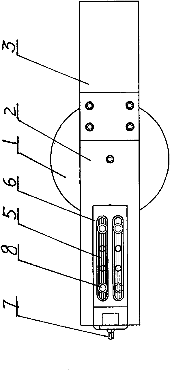
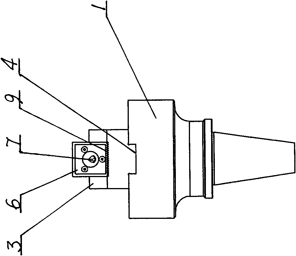
[0028] The present invention comprises a knife handle 1, a support rod 2 is arranged in a guide groove 4 at the end of the knife handle 1, one end of the support rod 2 is a balance weight 3, the other end of the support rod 2 is provided with a sliding knife rod 6, and the outer surface of the sliding knife rod 6 End is provided with boring tool 7.

[0029] The bottom of the sliding tool bar 6 is combined with the top of the support bar 2 in a zigzag shape 9; the sliding tool bar 6 and the supporting bar 2 are kept firm and stable during the working process of the boring tool 7.

[0030] Sliding knife bar 6 is provided with longitudinal groove 5, and support bar 2 is provided with corresponding fixing screw 8 of longitudinal groove 5; In order to adjust the position of fixing screw 8 of longitudinal groove 5 relative support bar 2, determine the boring on sliding knife bar 6. The machining position where the knife 7 is located.

[0031] One end of the sliding tool bar 6 is pr...


PUM


Abstract

The invention discloses a single-arm combined boring tool, which relates to the improvement on the structure of a boring tool. The invention provides the single-arm combined boring tool which is convenient in detachment, installation and use, simple in structure, wide in machining range. The boring tool comprises a tool holder and has the key structural points that: a supporting rod is arranged ina guide groove at a tool holder end; one end of the supporting rod is a counter weight; the other end of the supporting rod is provided with a sliding cutter bar; and the outer end of the sliding cutter bar is provided with the boring tool.

Description

Technical field: [0001] The present invention relates to the improvement of the boring tool structure. Background technique: [0002] At present, SANDVIK Cormant, the most famous tool manufacturer in the world, produces and processes large-diameter single-arm boring tools Φmax=981.6mm. 4 sets of heavy systems; (if processing to Φ1150mm, you need to add 2 sets) The fine boring unit is composed of a knife card, a fine boring head, and an extended slider, which is troublesome to combine. And only fine boring can be achieved. [0003] The double-edged large-aperture boring tool Φmax=810mm produced by the domestic Chengdu Measuring Tool and Cutting Tool Factory has a simple structure, but the connection with the handle is slightly complicated, and the double-edged structure; virtually increases the manufacturing process and cycle, and the structure is heavy. Φ490-Φ810 need 3 sets of boring tool systems (if machining Φ1150mm, 3 sets are needed). [0004] The common disadvantage...

Claims


Application Information

Patent Timeline
Patent Type & Authority Applications(China)
IPC IPC(8): B23B29/02B23B27/00
Inventor 毕伟达赵光辉蒋晓妍王强
Owner NFC (SHENYANG) METALLURGICAL MACHINERY CO LTD
Why Eureka
Try Eureka