Self-driven air charging valve

An inflatable valve, self-operated technology, used in the field of rubber-lined butterfly valves, can solve the problems of difficult control of sealing interference and large opening and closing torque.

Active Publication Date: 2010-03-17
JIANGSU SHENTONG VALVE
View PDF0 Cites 1 Cited by
  • Summary
  • Abstract
  • Description
  • Claims
  • Application Information

AI Technical Summary

Problems solved by technology

[0003] In order to overcome the existing rubber-lined butterfly valve sealing interference is difficult to control, the

Method used


Image

  • Self-driven air charging valve
  • Self-driven air charging valve

Examples


Embodiment Construction

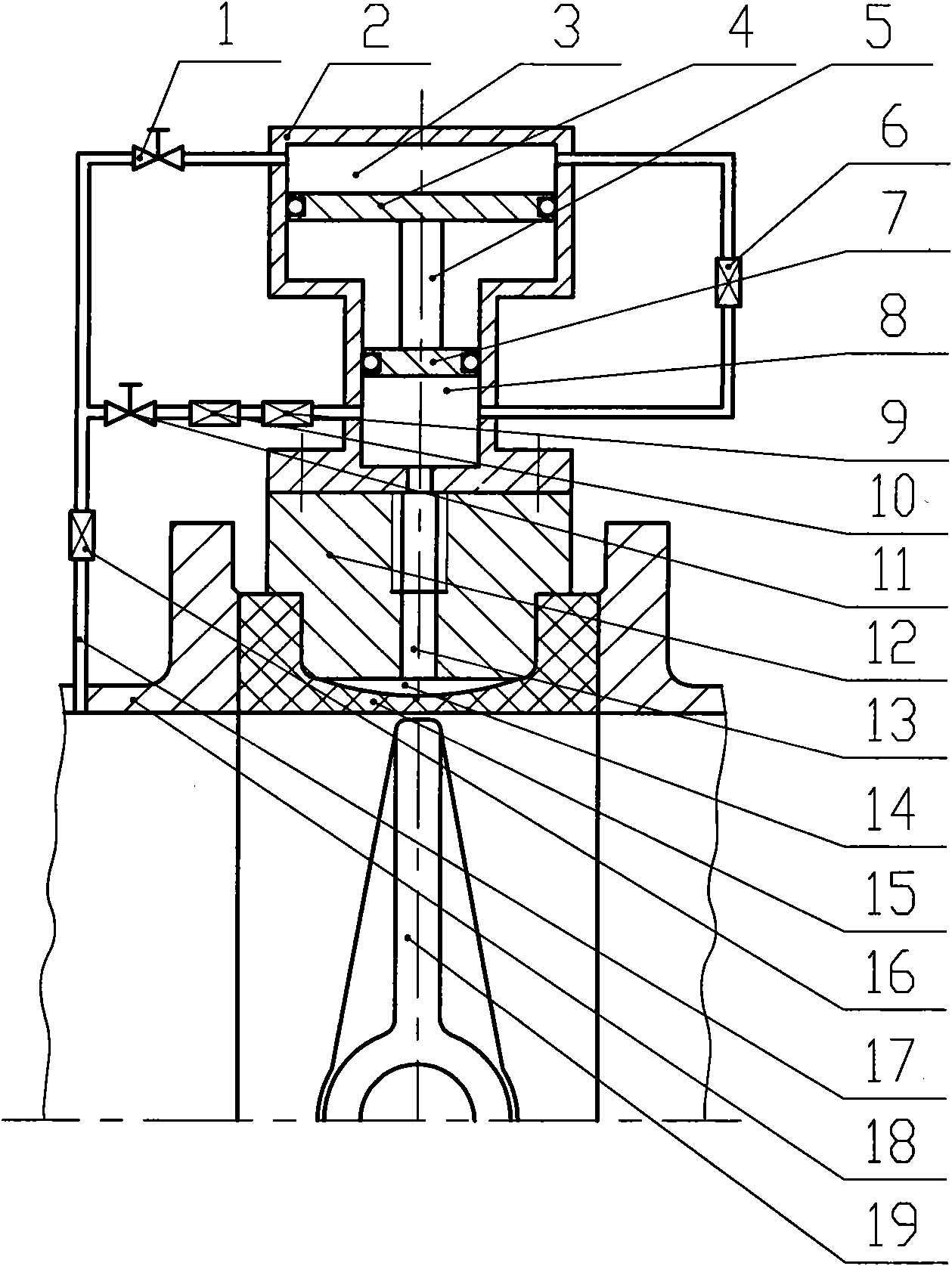
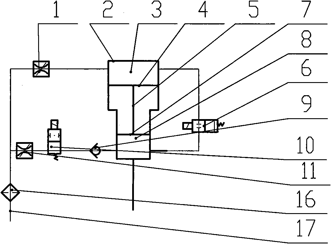
[0011] Such as figure 1 , 2 As shown, a self-operated inflation valve includes a valve body 12, a rubber valve seat 15, and a butterfly plate 19. The rubber valve seat 15 is installed in the valve body 12, and the valve body 12 has an air inlet 13, which is connected to the valve body 12. It communicates with the air bag cavity 14 formed between the rubber valve seat 15; a cylinder 2 is also installed above the air intake hole 13, and the cylinder 2 is divided into two chambers up and down, the diameter of the upper chamber 3 is greater than the diameter of the lower chamber 8, and there is an upper chamber in the upper chamber 3. Piston 4, lower piston 7 is arranged in the lower chamber 8, and upper piston 4 is connected with lower piston 8 by connecting rod 5; On the pipeline 18, a trachea 17 is also installed, and the trachea 17 is divided into upper and lower roads, and the upper road is equipped with a regulating valve-1 and The upper chamber 3 of the cylinder 2 communic...


PUM


Abstract

The invention provides a self-driven air charging valve, which comprises a valve body, a rubber valve seat and a butterfly plate, wherein the rubber valve seat is arranged in the valve body; the valvebody is provided with an air inlet communicated with an air bag cavity formed between the valve body and the rubber valve seat; an air cylinder is also arranged above the air inlet; the air cylinderis divided into an upper cavity and a lower cavity; the diameter of the upper cavity is larger than that of the lower cavity; the inside of the upper cavity is provided with an upper piston, the inside of the lower cavity is provided with a lower piston, and the upper piston is connected with the lower piston through a connecting rod; an air pipe is also arranged on a pipeline; the air pipe is divided into an upper path and a lower path; the upper path is provided with a regulating valve 1 communicated with the upper cavity of the air cylinder, the lower path is serially connected with the regulating valve 2, a solenoid valve 1 and a check valve which are communicated with the lower cavity of the air cylinder; and the upper cavity at the other side of the air cylinder is communicated withthe lower cavity through the air pipe, and the air pipe is provided with a solenoid valve 2. The self-driven air charging valve has the advantages that a certain gap is reserved among seal pairs in the process of opening and closing the valve to open and close the valve in the way of zero driving torque; and the air charging valve inflates air through the pressure of media in the pipeline withoutadditional energy sources.

Description

technical field [0001] The invention relates to a valve device, in particular to a rubber-lined butterfly valve. Background technique [0002] The sealing of the rubber-lined butterfly valves currently used in various industries is realized by the extrusion deformation between the rubber valve seat and the butterfly plate, the sealing interference is difficult to control, and the opening and closing torque is large. Contents of the invention [0003] In order to overcome the shortcomings of the existing rubber-lined butterfly valve, which are difficult to control the sealing interference and have a large opening and closing torque, the invention provides a butterfly valve without opening and closing torque. [0004] The technical solution adopted by the present invention to solve the technical problem is a self-operated inflatable valve, which includes a valve body, a rubber valve seat, and a butterfly plate. The rubber valve seat is installed in the valve body. It commun...

Claims


Application Information

Patent Timeline
IPC IPC(8): F16K1/228F16K27/02
Inventor 张逸芳陆平
Owner JIANGSU SHENTONG VALVE
Why Eureka
Try Eureka