Strut type shuttle valve

A shuttle valve and spool technology, applied in the field of spool type shuttle valve, can solve the problems of the main spool that is easy to blow-by gas and easy to get stuck, and achieves the effect of solving the blow-by gas and avoiding direct impact.

Active Publication Date: 2010-03-17
FESTO CHINA AUTOMATION MFG
View PDF0 Cites 6 Cited by
  • Summary
  • Abstract
  • Description
  • Claims
  • Application Information

AI Technical Summary

Problems solved by technology

[0004] Aiming at the deficiencies of the above-mentioned prior art, the technical problem to be solved by the present invention is to provide a spool type shuttle valve, which solves the problems that the existing shuttle valve is prone to gas blow-by and the main valve core is easily stuck.

Method used


Image

  • Strut type shuttle valve
  • Strut type shuttle valve
  • Strut type shuttle valve

Examples


Embodiment Construction

[0018] The preferred embodiments of the present invention will be described in detail below in conjunction with the accompanying drawings.

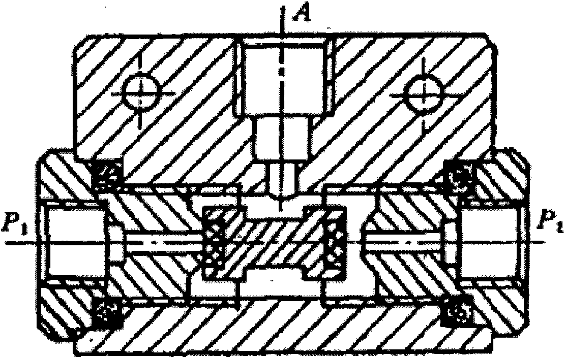
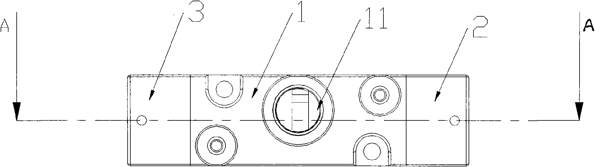
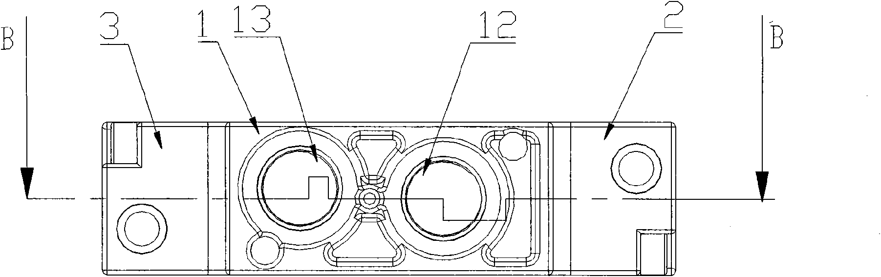
[0019] Such as figure 2 , 3 , 4, the spool type shuttle valve includes a main valve body 1, and the main valve body 1 is provided with an air outlet 11, a first air inlet 12 and a second air inlet 13. Both ends of the main valve body 1 are respectively provided with a pilot valve 2, 3 as a thrust device, and the pilot valves 2, 3 are connected with the main valve body 1. The thrust device can also be an electromagnet, an electromagnetic pilot valve or a manual device, as long as the device can make the main valve core in the main valve body move back and forth in the valve cavity.

[0020] Such as Figure 5 As shown, the first air inlet 12 and the second air inlet 13 are arranged in the axial direction of the valve cavity 15, and the valve cavity 15 of the main valve body 1 is fixedly provided with a first sealing ring 16, a second se...


PUM


Abstract

The invention discloses a strut type shuttle valve comprising a main valve body provided with a first air inlet, a second air inlet and an air outlet, and a main valve plug which can move between a first position and a second position is arranged in the valve cavity of the main valve body; when the main valve plug is arranged on the first position, the first air inlet is communicated with the airoutlet, and the second air inlet is not communicated with the air outlet; when the main valve plug is arranged on the second position, the second air inlet is communicated with the air outlet, and thefirst air inlet is not communicated with the air outlet. Two ends of the main valve body are respectively provided with a thrust device, two thrust devices are respectively connected with two ends ofthe main valve plug, and the thrust devices can push the main valve plug to move. The main valve plug of the shuttle valve with the structure is not directly driven by air inflow from the air inlet,thus avoiding direct shock to the main valve plug by the air inflow; therefore, the stuck phenomenon of the main valve plug can be avoided, and the problem of blow-by gas between air inlets can be effectively solved.

Description

technical field [0001] The invention relates to a valve, in particular to a spool type shuttle valve. Background technique [0002] The shuttle valve is a straight-stroke valve, which is equivalent to a combination of two check valves, and its function is equivalent to an "OR gate". Its structure is generally as figure 1 As shown, it includes two air inlets P1 and P2, and one outlet A, where both P1 and P2 can be communicated with A port, but P1 and P2 are not communicated. Any port in P1 and P2 has signal input, and port A has output. If both P1 and P2 have signal input, the gas signal on the side that is added first or the side with high signal pressure is output through A, and the other side is blocked. Only when there is no signal input from P1 and P2, A has no signal output. Because the shuttle valve can input the control signal into the control actuator in an orderly manner, and has the advantages of small size and easy installation, the shuttle valve has been widel...

Claims


Application Information

Patent Timeline
Patent Type & Authority Applications(China)
IPC IPC(8): F16K11/07F16K31/12
Inventor 周潮
Owner FESTO CHINA AUTOMATION MFG
Why Eureka
Try Eureka