Solar collector

A solar collector and sunlight technology, applied in the field of solar collectors, can solve problems such as low heat collection efficiency, and achieve the effects of improving heat absorption efficiency and reducing reflection

Inactive Publication Date: 2010-03-17
YIKEBO ENERGY TECH SHANGHAI
View PDF3 Cites 11 Cited by
  • Summary
  • Abstract
  • Description
  • Claims
  • Application Information

AI Technical Summary

Problems solved by technology

[0003] The object of the present invention is to provide a solar heat collector, in ord

Method used


Image

  • Solar collector

Examples


Embodiment approach

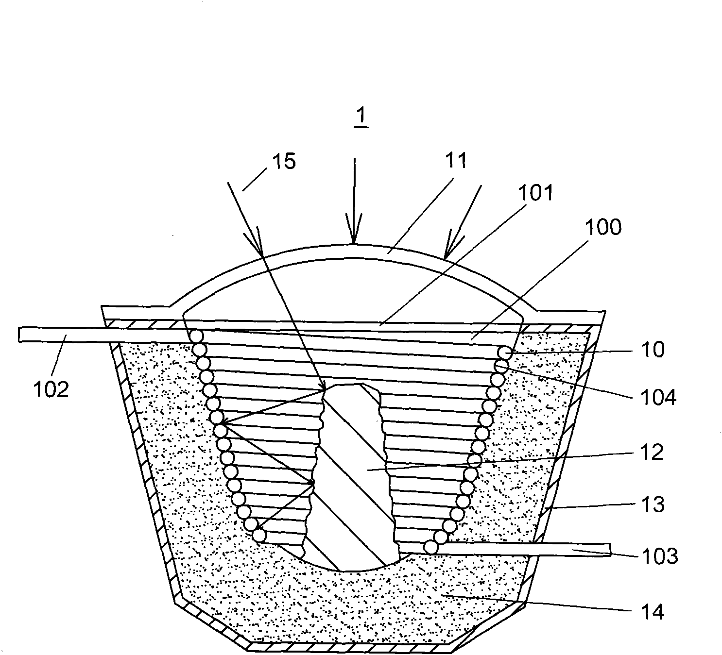
[0016] see figure 1 As shown, it is a schematic cross-sectional view of a solar heat collector 1 implementing the present invention. The solar heat collector 1 includes a housing 13. During specific implementation, the outer surface of the housing 13 is streamlined (such as semicircular or ellipse), so as to reduce air resistance, and the housing 13 is internally arranged with heat-absorbing tubes 10, the heat-absorbing tubes 10 are spirally arranged to form a cavity 100, and one end of the cavity 100 is provided with a The opening 101 is used to allow the sunlight 15 collected by the solar concentrator (not shown) to enter the cavity 100 from the opening 101 so as to be absorbed by the heat absorbing pipe 10 . In addition, the surface of the heat-absorbing tube 10 is provided with a selective absorbing coating 104, such as an electroplated black chrome layer, so that the absorbing coating 104 of the heat-absorbing tube 10 only absorbs visible light, does not absorb infrared l...


PUM


Abstract

The invention relates to a solar collector comprising a heat absorption pipe, wherein, the heat absorption pipe is spirally arranged to form a cavity; one end of the cavity is provided with an openingfor receiving the concentrated incident sunlight; one end of the heat absorption pipe is connected with a working fluid inlet pipe, and the other end is connected with a working fluid outlet pipe; atransparent cover body is covered outside the opening, and the transparent cover body protrudes in the direction deviating from the opening and forms a camber, thus, the concentrated incident sunlightcan transmit the transparent cover body in the direction perpendicular to the camber and enters the cavity so as to reduce the reflection; and meanwhile, the opening is closed by the transparent cover body so as to prevent sand, dust and other impurities from entering the collector and also prevent the heat energy in the collector from being taken out of the collector along with the air circulation, thereby being favorable for enhancing the heat absorption efficiency of the collector.

Description

【Technical field】 [0001] The invention relates to a solar heat collector and belongs to the technical field of solar heat utilization. 【Background technique】 [0002] The prior art related to the present invention can refer to the PCT published patent application WO96 / 12918, which discloses a heat collector comprising a cylindrical shell, and heat-absorbing pipes are arranged on the inner surface of the cylindrical shell, The outer surface of the heat-absorbing tube is coated with a high-temperature solar selective absorption coating, and the two ends of the heat-absorbing tube are connected with a working fluid outlet pipe and an inlet pipe, and one end of the shell is opened to receive concentrated incident light. When the concentrated sunlight enters the opening of the shell, the solar energy is converted into heat energy through the absorbing coating coated on the outer surface of the heat-absorbing tube, thereby heating the working fluid in the heat-absorbing tube. The ...

Claims


Application Information

Patent Timeline
IPC IPC(8): F24J2/24F24J2/50F24J2/46F24J2/48F24J2/51F24S10/70
CPCY02E10/44
Inventor 项晓东张融肖丰
Owner YIKEBO ENERGY TECH SHANGHAI
Why Eureka
Try Eureka