
Heat exchanger capable of improving drainage performance

A heat exchanger, horizontal technology, used in heat transfer modification, heat exchange equipment, evaporators/condensers, etc., can solve the problems of not easy to discharge, easy accumulation of condensed water, etc., to improve drainage performance, improve surface Effect of heat exchange performance

Active Publication Date: 2010-03-17
SANHUA HANGZHOU MICRO CHANNEL HEAT EXCHANGER
View PDF0 Cites 13 Cited by
  • Summary
  • Abstract
  • Description
  • Claims
  • Application Information

AI Technical Summary

Problems solved by technology

[0008] In addition, the surface tension in the inner area of ​​the fin 1' and the welding area with the flat tube 2' is very high, and the condensed water is easy to accumulate in these areas and is not easy to discharge

Method used


Image

  • Heat exchanger capable of improving drainage performance
  • Heat exchanger capable of improving drainage performance
  • Heat exchanger capable of improving drainage performance

Examples


Embodiment Construction

[0028] Embodiments of the present invention are described in detail below, examples of which are shown in the drawings, wherein the same or similar reference numerals designate the same or similar elements or elements having the same or similar functions throughout. The embodiments described below by referring to the figures are exemplary only for explaining the present invention and should not be construed as limiting the present invention.

[0029] In the description of the present invention, the orientation or positional relationship indicated by the terms "longitudinal", "transverse", "vertical", "horizontal", etc. is based on the orientation or positional relationship shown in the drawings, and is only for the convenience of describing the present invention. The invention does not require that the invention must be constructed and operated in a particular orientation, and thus should not be construed as limiting the invention.

[0030] Hereinafter, a heat exchanger accord...


PUM


Abstract

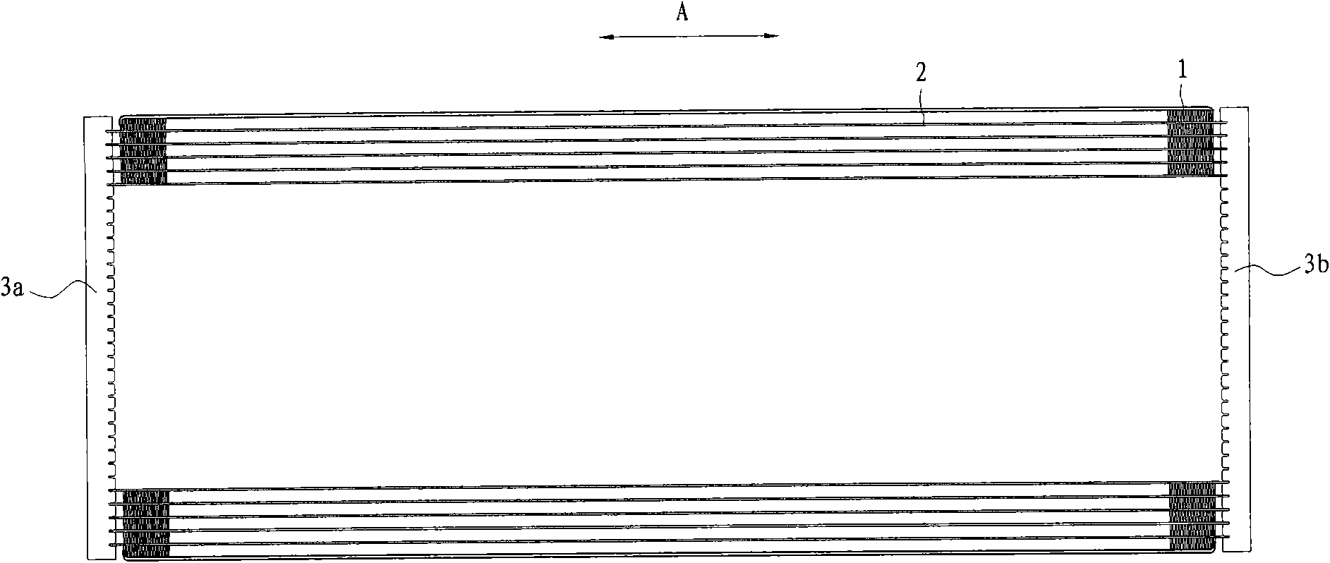
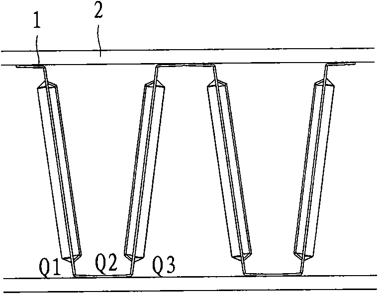
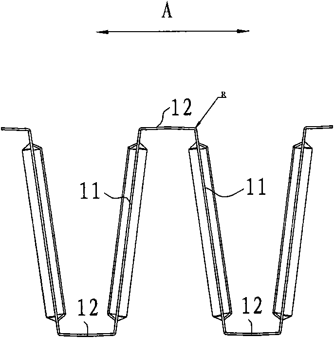
The invention discloses a heat exchanger, comprising a first collecting pipe, a second collecting pipe, a flat pipe and a fin, wherein, the first collecting pipe is arranged vertically; the second collecting pipe is arranged in parallel with and opposite to the first collecting pipe and a preset distance is spaced out therebetween; the flat pipe is arranged between the first collecting pipe and the second collecting pipe horizontally and the two ends are respectively communicated with the first collecting pipe and the second collecting pipe; the fin is generally in a corrugated shape and is arranged between adjacent flat pipes; the fin comprises a straight line segment and a join segment which are connected in turn to ensure that the join segment forms a wave crest and a wave trough; the first end of the fin stretches out from one side of the flat pipe along the transverse direction; and the join segment in the first end part is removed. The heat exchanger in the invention can improvethe drainage performance, improve the surface heat exchanging of the heat exchanger and reduce the waste work of an air blower.

Description

technical field [0001] The invention relates to a heat exchanger, in particular to a microchannel heat exchanger capable of improving the performance of discharging condensed water. Background technique [0002] For example, when a parallel flow heat exchanger is used as an evaporator or a heat pump heat exchanger, condensed water will be generated on the surface. In order to improve the performance of the heat exchanger to discharge condensed water, the parallel flow heat exchanger usually adopts horizontal headers and flat tubes Install vertically between headers. [0003] However, the above-mentioned conventional arrangements of headers and flat tubes are not suitable for certain types of heat exchangers, such as prolate heat exchangers (ie, heat exchangers whose length is much greater than their height). [0004] For flat and long heat exchangers, if the above-mentioned traditional setting method is adopted, the following problems will be brought about: [0005] The he...

Claims


Application Information

Patent Timeline
IPC IPC(8): F25B39/02F28F3/02F28F13/04
Inventor 刘华钊黄宁杰
Owner SANHUA HANGZHOU MICRO CHANNEL HEAT EXCHANGER
Learn More