Microstrip transmission line impedance parameter test method

A technology of microstrip transmission line and testing method, which is applied in the direction of measuring resistance/reactance/impedance, measuring device, measuring electrical variables, etc., which can solve the problems of unmeasured or inaccurate measurement, large parasitic inductance, small mutual inductance of coupled differential impedance lines, etc. problem, to achieve the effect of accurate test

Active Publication Date: 2010-03-17
SHENZHEN BOMIN ELECTRONICS
View PDF0 Cites 25 Cited by
  • Summary
  • Abstract
  • Description
  • Claims
  • Application Information

AI Technical Summary

Problems solved by technology

Can the distribution parameters of the microstrip transmission line and the coupled differential impedance line in the PCB circuit impedance strip be measured with this 4TP structure with good performance? The actual situation is that in addition to being able to measure the distributed capacitance of the microstrip transmission line and the distributed self-capacitance parameters of the coupled differential impedance line, other parameters are not measurable or inaccurate, such as the inductance of the microstrip transmission line and the self-capacitance of the coupled differential impedance line. The inductance is uncertain, and the mutual inductance and mutual capacitance parameters of the coupled differential impedance line cannot be measured. This is because the impedance line is usually the same length as the single-ended impedance test strip and the coupled differential impedance test strip used to test the PCB circuit. At about 15cm, the outer conductor between the 4TP structure Hp, Hc cable pair and Lp, Lc cable pair should be connected with a wire longer than 15cm, which will bring a large parasitic inductance. At the same time, the position and shape of the connecting wire are different. The inductance value will change, so it is difficult to measure the distributed inductance of the microstrip transmission line with only tens of nH and the distributed self-inductance of the coupled differential impedance line. The mutual inductance of the coupled differential impedance line is even smaller, and it is impossible to measure it separately , to test the mutual capacitance of the coupled differential impedance line, you can only connect the two test terminals of the 4TP structure to the two coupled lines respectively, but what is measured in this way is not the mutual capacitance, but the mutual capacitance between the two coupled lines and the self-capacitance of the two coupled lines in series The result of the parallel connection after the phase is also affected by the dielectric properties of the support that is in contact with the metal ground plate of the impedance bar

Method used


Image

  • Microstrip transmission line impedance parameter test method
  • Microstrip transmission line impedance parameter test method
  • Microstrip transmission line impedance parameter test method

Examples


Embodiment Construction

[0046] The present invention will be further described below in conjunction with the accompanying drawings:

[0047] Microstrip transmission line impedance parameter test method, including the following steps:

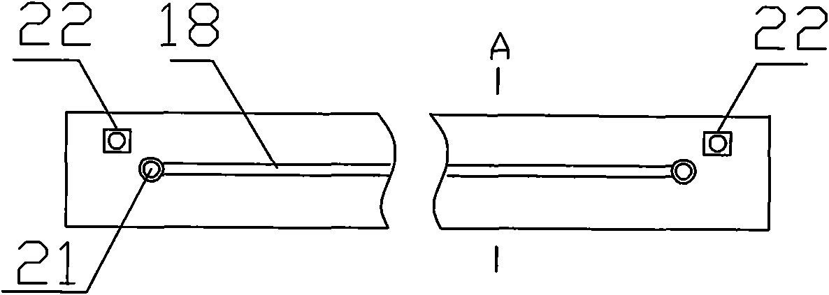
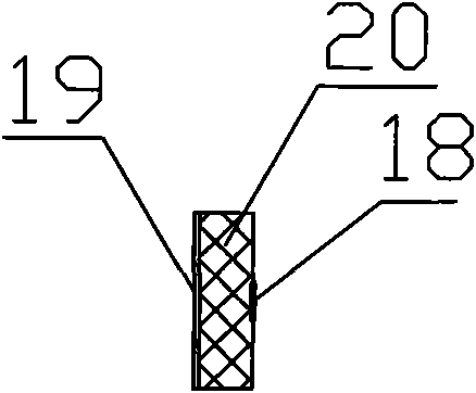
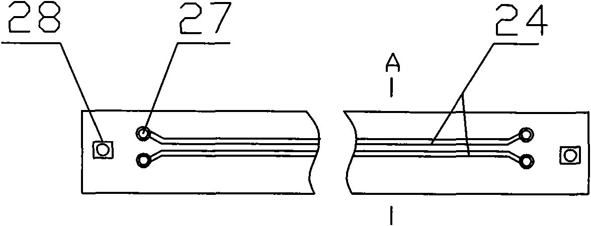
[0048] a, using the operating frequency The small inductance and small capacitance precision parameter tester and two pairs of distributed parameter impedance test cables, each pair of cables has a test probe and a ground probe, which are used to distribute parameters of the microstrip transmission line of the single-ended impedance test strip and the coupled differential impedance test strip The test is carried out to calculate the single-ended impedance and coupled differential impedance of the microstrip transmission line.

[0049] b. Perform short-circuit and open-circuit correction on the parameter tester;

[0050] c. Determine the correction coefficient K value when the ground probe is used as a test probe: ground the two test probes, connect the two ground pr...


PUM


Abstract

The invention discloses a microstrip transmission line impedance parameter test method; a low-inductance small-capacitance precise parameter tester with working frequency f which is more than (R / 2.81L) Hz and a test cable which is provided with a test probe and a grounded probe are adopted, and a sing-ended impedance test strip which is composed of two non-coupling microstrip transmission lines with a distance which is more than two times of line width, and a differential impedance test strip which is composed of two coupled microstrip transmission lines are used; by adopting the testing method, total distribution parameters of the microstrip transmission line can be measured accurately, so as to realize the purpose of accurately testing characteristic impedance of the microstrip transmission line with a distributed parameter method.

Description

technical field [0001] The invention relates to the technical field of electrical variable parameter testing, in particular to a method for testing impedance parameters of a microstrip transmission line. Background technique [0002] Since the impedance line in the PCB circuit is usually very short, it is very difficult to directly test the impedance from the PCB circuit. Therefore, a certain length of impedance line is specially designed on the printed board for processing the PCB circuit. For testing, their physical The size is the same as the corresponding impedance line in the PCB circuit, and it is processed together with the PCB circuit under the same process conditions. This impedance line for testing is cut to form an impedance test strip. The test of the characteristics reflects the characteristics of the corresponding impedance lines in the PCB circuit. Impedance test strips are divided into single-ended impedance test strips and coupled differential impedance tes...

Claims


Application Information

Patent Timeline
Patent Type & Authority Applications(China)
IPC IPC(8): G01R27/02G01R27/26
Inventor 阳泽彬
Owner SHENZHEN BOMIN ELECTRONICS
Why Eureka
Try Eureka