Front-opening unified pod with wafer constraints arranged on door

A front-opening, wafer box technology, applied in the direction of electrical components, semiconductor/solid-state device manufacturing, circuits, etc., can solve the problems of complex structure of wafer restraints, contamination of wafers, poor airtightness, etc.

Active Publication Date: 2010-03-17
GUDENG PRECISION IND CO LTD
View PDF0 Cites 3 Cited by
  • Summary
  • Abstract
  • Description
  • Claims
  • Application Information

AI Technical Summary

Problems solved by technology

[0004] According to the wafer box of the prior art, the structure of the wafer limiting part is complex and it is easy to cause problems such as poor airtightness and particle dust. A main purpose of the present invention is to provide a wafer box with a wafer limiting part. The wafer limiting part of the wafer box Placed on both sides of the inner surface of the door close to the center, each wafer restricting piece has multiple contact ends, in addition to preventing the wafer from being dislocated or moving toward the center of the opening due to vibration, it can also restrict the movement to the two sides of the opening Movement in the direction of the wafer can avoid the friction between the wafer and the wafer restraint to generate particulate dust and contaminate the wafer

Method used


Image

  • Front-opening unified pod with wafer constraints arranged on door
  • Front-opening unified pod with wafer constraints arranged on door
  • Front-opening unified pod with wafer constraints arranged on door

Examples


Embodiment Construction

[0052] In order to have a more complete and clear disclosure of the technical content used in the present invention, the purpose of the invention and the effects achieved, the detailed description is given below, and please also refer to the disclosed diagrams and figure numbers:

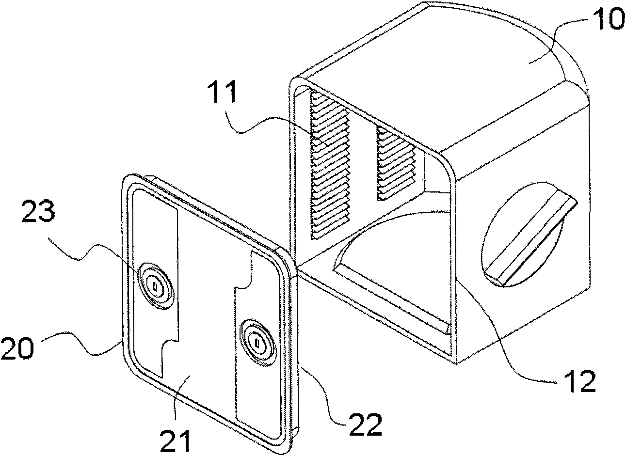
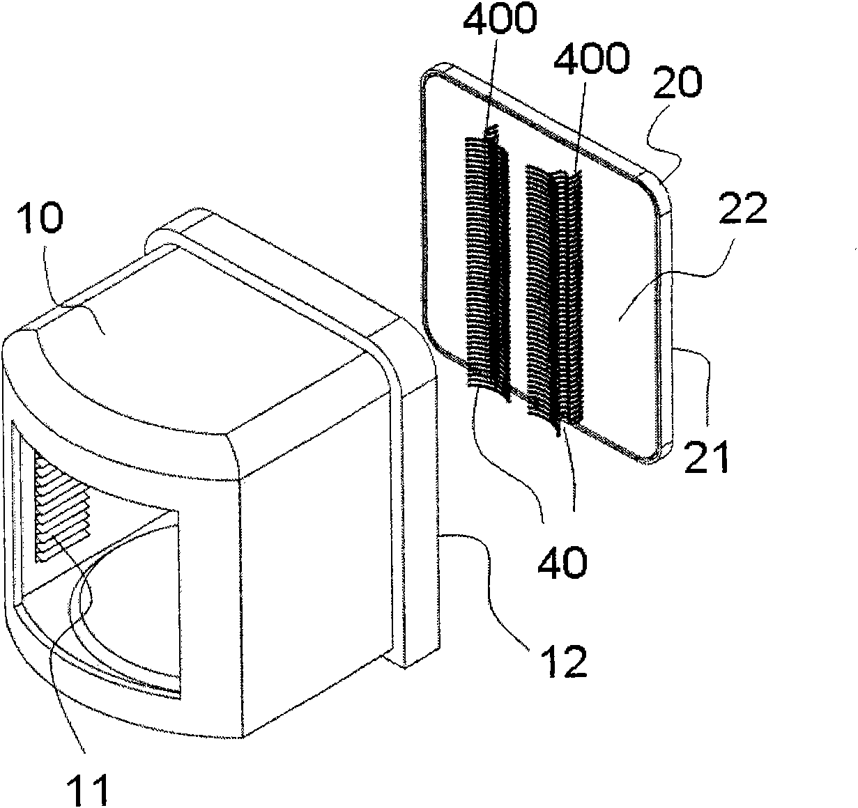
[0053] First, see image 3 Shown is a schematic diagram of the first wafer box of the present invention. This wafer box is a front-opening type wafer box, which mainly includes a box body 10 and a door body 20. A plurality of slots 11 are provided inside the box body 10 to accommodate a plurality of wafers, and on the inside of the box body 10 One of the sides has an opening 12 to provide input and output of wafers, and the door body 20 has an outer surface 21 and an inner surface 22, and the outer surface 21 of the door body 20 is configured with at least one latch opening (not shown in the figure). ), which is used to open or close the front-opening wafer box, and two rows of wafer restraint modu...


PUM


Abstract

The invention relates to a front-opening unified pod with wafer constraints arranged on a door, which comprises a pod body, wherein a lateral surface of the pod body is provided with an opening, the inside of the pod body is provided with a plurality of slots for accommodating a plurality of wafers, and a door body is combined with the opening of the pod body to protect the wafers in the pod body.The front-opening unified pod is characterized in that: a position adjacent to the center of the inner surface of the door body is provided with two rows of a plurality of spaced and aligned wafer constraints, wherein each wafer constraint is provided with a base; one end of the base is fixed on the inner surface of the door body, while the other end is connected with a crank arm; the crank arm is provided with a first contact end and a second contact end, and thus the wafer constraints can constrain the wafers to move towards the opening by the first contact ends and the second contact endssequentially.

Description

technical field [0001] The present invention relates to a wafer cassette, and more particularly to a wafer cassette having a wafer constraint having a plurality of contact ends for firmly restricting wafer movement. Background technique [0002] Semiconductor wafers will be transported to different workstations due to the need to go through various processes and to cooperate with process equipment. In order to facilitate the handling of the wafers and avoid contamination from the outside, a sealed container is often used for delivery by automated equipment. Please refer to figure 1 Shown is a schematic diagram of a wafer box in the prior art. This wafer box is a front opening type wafer box (Front Opening Unified Pod, FOUP), which has a box body 10 and a door body 20, and a plurality of slots 11 are provided inside the box body 10 to accommodate a plurality of wafers horizontally. And there is an opening 12 on one side of the box body 10 for carrying out and loading of wa...

Claims


Application Information

Patent Timeline
IPC IPC(8): H01L21/673
Inventor 林志铭潘冠纶
Owner GUDENG PRECISION IND CO LTD
Why Eureka
Try Eureka