Method and device for calibrating antennae

An antenna calibration and antenna technology, applied in antennas, diversity/multi-antenna systems, transmission monitoring, etc., can solve difficult and costly problems, and achieve the effect of avoiding high costs

Inactive Publication Date: 2010-03-17
CHINA ACAD OF TELECOMM TECH
View PDF0 Cites 27 Cited by
  • Summary
  • Abstract
  • Description
  • Claims
  • Application Information

AI Technical Summary

Problems solved by technology

[0006] The present invention provides an antenna calibration method and device to solve the probl

Method used


Image

  • Method and device for calibrating antennae
  • Method and device for calibrating antennae
  • Method and device for calibrating antennae

Examples


Embodiment Construction

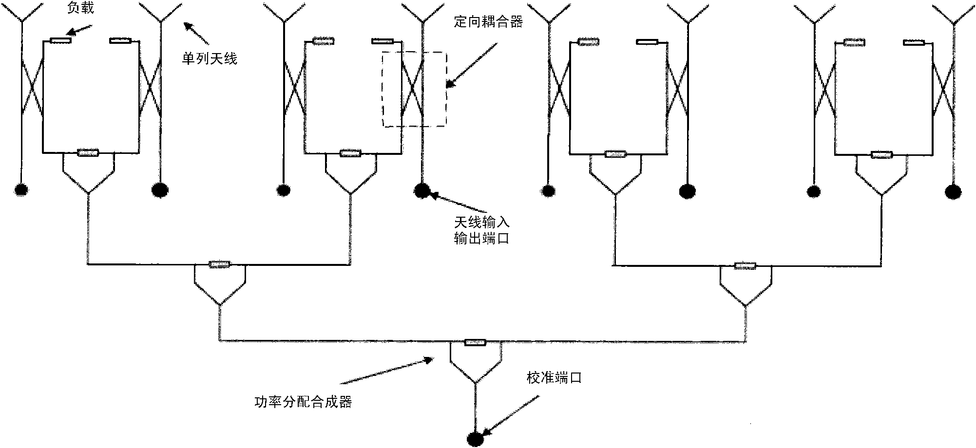
[0028] In a multi-antenna system, especially in the over-antenna technology of a TDD system, antenna calibration is very important. The existing technology often uses a calibration network to send and receive calibration signals through a unified calibration port to calibrate the transmit and receive channels of multiple antennas separately. However, this calibration scheme based on the calibration network is not only costly, but also for large spacing Antennas and remote antennas are difficult to implement.

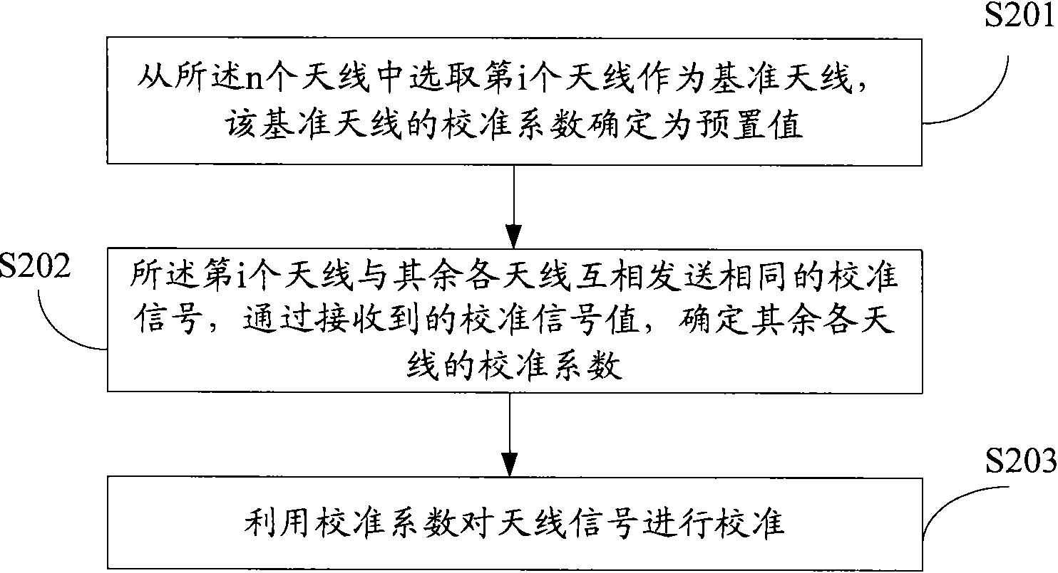
[0029] For this reason, the present invention proposes a kind of brand-new antenna calibration method, is used for calibrating n antennas, and said n is greater than or equal to 2, see figure 2 , the method includes the following steps:

[0030] S201: Select the i-th antenna from the n antennas as a reference antenna, and determine the calibration coefficient of the reference antenna as a preset value;

[0031] S202: The i-th antenna and the other antennas send the sa...


PUM


Abstract

The invention discloses a method and a device for calibrating antennae, which are used for calibrating n antennae, wherein n is more than or equal to 2. The method comprises the following steps: selecting the ith antenna from the n antennae as a reference antenna, and determining the calibration coefficient of the reference antenna as a preset value; sending the same calibrating signals between the ith antenna and the rest antennae, and determining the calibration coefficients of the rest antennae according to the received values of the calibration signals; and using the calibration coefficients to calibrate antenna signals. The method and the device need no calibration networks, in short, connections are unnecessary to be established between the antennae, namely a unified calibration portis not needed for receiving and sending the calibration signals, thereby avoiding the problems that the prior scheme has high cost and large implementation difficulties caused by the calibration networks.

Description

technical field [0001] The present invention relates to the technical field of wireless communication, in particular to an antenna calibration method and device. Background technique [0002] In smart antennas and multiple input output (Multi Input Multi Output, MIMO) systems, antenna calibration plays a very important role. This is due to the asymmetry of the uplink and downlink of the radio frequency channel of the antenna. The antenna transmission channel generally uses a high-power amplifier (Higher Power Amplifier, HPA) for transmission, and a low-noise amplifier (Low-noise Amplifier, LNA) for reception. These two active RF devices are completely independent, resulting in inconsistencies between the transmission channel and the reception channel. . [0003] For a Time Division Duplex (TDD) system, it is considered that the uplink and downlink channels of the system are the same, and the downlink channel is often estimated based on the uplink channel of the system. Th...

Claims


Application Information

Patent Timeline
IPC IPC(8): H04B17/00H04B7/02H04B7/005
CPCH01Q3/267
Inventor 吴柯维李传军孙长果
Owner CHINA ACAD OF TELECOMM TECH
Why Eureka
Try Eureka