

Obstacle detector, wireless receiver, wireless transmitter, and wireless communication system
A technology for obstacle detection and wireless transmission, which is applied in satellite radio beacon positioning systems, radio wave measurement systems, measurement devices, etc., can solve the problem of not being able to quickly follow the rapid changes of radio waves, not being able to improve the quality of radio wave reception, and not being able to use the receiving antenna selection Technology or diversity technology and other issues to achieve the effect of improving the quality of reception
- Summary
- Abstract
- Description
- Claims
- Application Information
AI Technical Summary
Problems solved by technology
Method used
Image

Examples
Embodiment approach 1
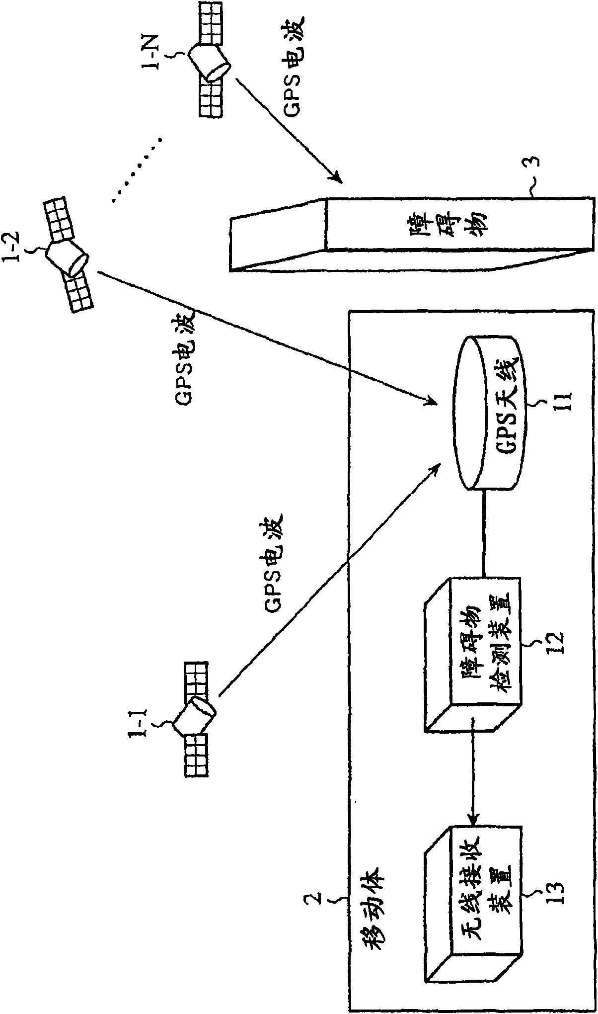
[0024] figure 1 It is a configuration diagram showing a wireless communication system according to Embodiment 1 of the present invention.
[0025] exist figure 1 Among them, the GPS satellites 1-1 to 1-N are satellites revolving around the earth, and transmit GPS radio waves with GPS data superimposed. The GPS data not only includes their own operation information (indicating on which orbit the GPS satellite orbits the earth) surrounding operation information), but also includes the operation information of all GPS satellites orbiting above the earth.
[0026] exist figure 1 In the figure, N GPS satellites are shown, but since there are GPS satellites orbiting to positions invisible from the mobile body 2, actually more than N GPS satellites are orbiting the earth.
[0027] In addition, the GPS radio waves transmitted from the GPS satellites 1 - 1 to 1 -N are microwaves with high rectilinear propagation properties. Therefore, when there is no obstacle in the straight trans...
Embodiment approach 2
[0088] In the first embodiment described above, the obstacle detection unit 25 of the obstacle detection device 12 calculates the direction in which the obstacle 3 exists, and outputs the obstacle information indicating the direction in which the obstacle 3 exists to the wireless receiving device 13. example, but it is also possible that the obstacle detection unit 25 records the trajectory of the current position measured by the position measurement unit 23 and the change in the direction in which the obstacle 3 exists, and based on the trajectory of the current position and the change in the direction in which the obstacle 3 exists , to determine the shape and position of the obstacle 3 .
[0089] Hereinafter, the processing content of the obstacle detection unit 25 will be specifically described.
[0090] Figure 6 It is an explanatory diagram showing the shape and position of the obstacle 3 . which is, Figure 6 It is an explanatory diagram of a two-dimensional display of...
Embodiment approach 3
[0101] In Embodiment 1 of the above formula, the radio wave reception processing unit 33 of the radio receiving device 13 lowers the sensitivity of the radio receiving antenna 31-1 facing the direction where the obstacle 3 exists and increases the sensitivity of the radio wave receiving antenna 31-1 facing the direction where the obstacle 3 does not exist. The radio wave receiving processing unit 33 may combine the radio waves received by the radio receiving antennas 31-1 to 31-M to improve radio wave reception. quality.
[0102] Hereinafter, the processing content of the radio wave reception processing part 33 is demonstrated concretely.
[0103] A radio wave arriving from a direction where the obstacle 3 does not exist is highly likely to be a direct wave, and a radio wave arriving from a direction where the obstacle 3 is present is highly likely to be a reflected wave of the obstacle 3 .
[0104] Therefore, the radio wave reception processing unit 33 recognizes the radio w...
PUM
 Abstract
Description
Claims
Application Information